User Tools
Sidebar
Table of Contents
Peripheral Interaction Project
Overview
The goals of this project are the following:
1) Modify the control board of a remote control car's handset to accept input from the parallel port of a computer.
2) Control the vehicle using software written in C.
Components
1) Remote control car and controller that uses the Realtek TX2 transmitter controller chip.
2) (4) 1k ohm resistors.
3) (4) MPSA13 NPN transistors or equivalent.
4) Soldering iron, solder and flux.
5) Printer port cable.
Realtek TX2 Transmitter Chip
The first step is to disassemble the handset and remove the motherboard.
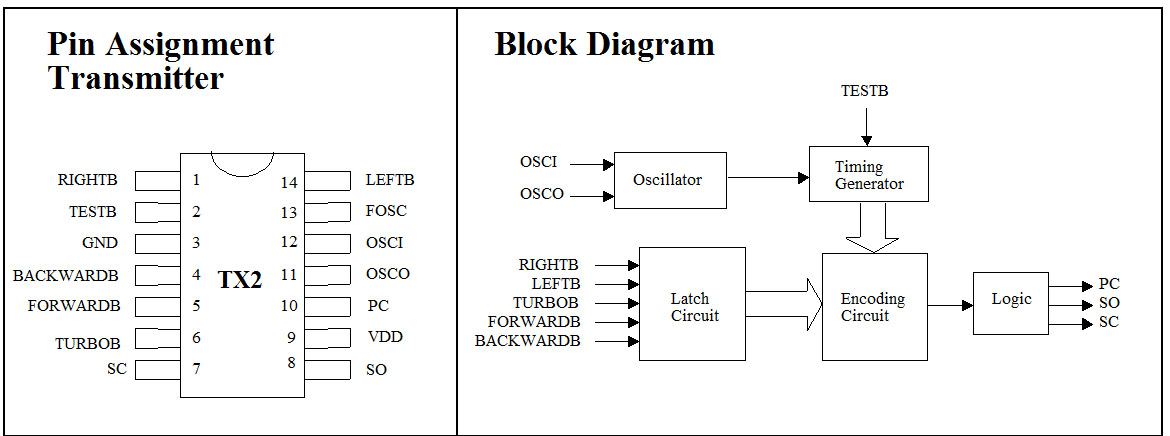
The first step I took was to identify the components and obtain their specifications to identify functions. After disassembling the remote handset, I found that the on board controlling IC was a Realtek TX2 chip. This is apparently a very common chip that is used in many remote control vehicles.
The chip has pins that correspond to the car's basic functionality - such as forward, reverse, left and right. There is also a function for “turbo” - but this is hard-wired to be always active on the motherboard. Turbo could be enabled by cutting the trace to ground from the chip's pin and controlling it via a transistor if desired.
I will only go over the basic functions of the chip, if you would like more detailed information the specification sheet can be found here: http://www.adrirobot.it/zap_toys/RX_TX.pdf
Here is the basic pinout of the chip with the manufacturers designations.
Again, it is only the movement and power functions that we will be concerned with in this project.
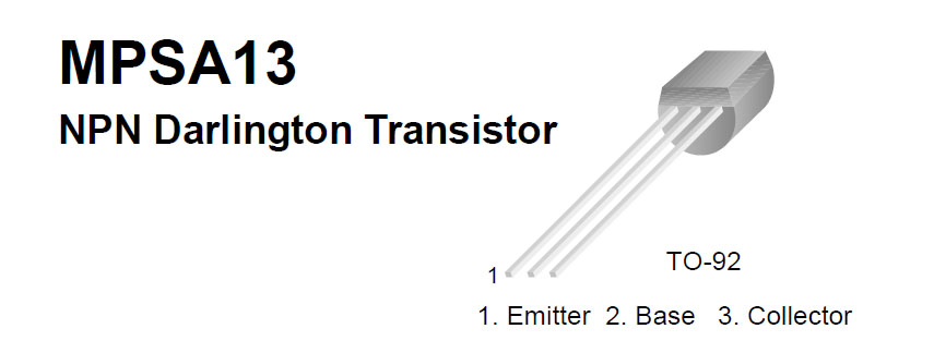
MPSA13 NPN Transistor
To enable a function on the motherboard, the corresponding function pin on the chip must be grounded. This is done on the handset by use of a toggle switch which pushes a contact to ground. To remotely control the handset we must find another way to do this. The easiest way is to use a transistor as a switch.
I found a bunch of MPSA13 transistors in “the pile” that work well in this application.
The key to making this work is by attaching the emitter pin to the bus ground of the remote mother board, the collector pin to the IC side of the contact, and the base pin to the corresponding data line from the printer port cable. IMPORTANT I learned the hard way by burning out a few transistors that you MUST put a 1k ohm resistor in series with the base pin on the transistor, if you do not, you'll supply too much voltage to it resulting in overheating and burn-out, which in short, is not good :D
The Layout
The key to making this work is to plan it all in advance. I drew multiple diagrams to make life easier.
First is the circuit layout on the transmitter board.
This is an overview of my “plan” - with a detail of how each transistor gets soldered in. You can wing it, but doing so will result in mass confusion and potentially letting the “magic smoke” out of the wires, oh yeah, and most likely causing damage to your computer!
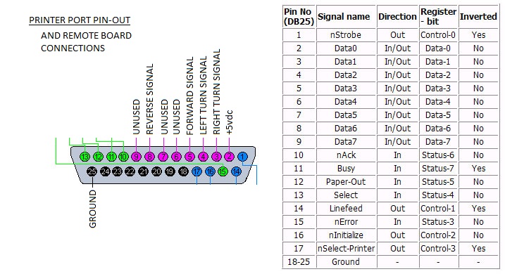
The next step of the plan is determining how to integrate the modified transmitter board with the printer port cable. Again, another diagram..
We will be using pins 2 through 9 (data bit 0 - 7) for our control functions. Here's the breakdown
Pin2 - Data-0 - +5vdc
Pin3 - Data-1 - Right Turn Function
Pin4 - Data-2 - Left Turn Function
Pin5 - Data-3 - Forward Function
Pin8 - Data-6 - Reverse Function
Pin25 - Ground
It is critically important to use a continuity tester to identify and mark each wire!! Use masking tape or some other way to identify the pin/port on the transmitter side of the cable.
Making the Modifications
So, the planning phase is over, time to get our hands dirty! Try not to drink alot of coffee before this step as it involves some soldering.
The first thing that I did was solder in the power to the transmitter board, this requires identifying the battery lead connections and performing the following operations:
1) Solder the wire from Pin2 (+5vdc) to where the positive battery lead is attached to the transmitter board.
2) Solder the wire from Pin25 (ground) to where the negative battery lead is attached to the transmitter board.
Next step is to attach the transistors to the system. I found the easiest way was to solder the resistor to the middle pin of the transistor (the base pin) ahead of time, that way you can use it as a “handle” to position the emitter and collector pins later on. Also, by bending the base pin on the transistor up (towards the flat on the transistor), it moves it way from the other pins and helps prevent shorting the pins out.
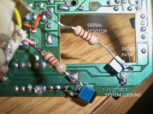
The key to soldering the transistors in right is to identify the transmitter board ground bus, this can be done easily by following the trace from the negative battery connection to each switch. At this position solder the transistor's emitter, on the opposite side of the switch solder the collector. Be sure to keep all connections separate to prevent grounding/shorting. This is the most difficult part, but luckily you have me to guide you through it :D
Below is my connections, as I prove through this picture, I am by no means a professional solderer!
Driver Software (no pun intended)
The tough part is over! Now onto making the car drive.
As before, the next step requires some planning. The vehicle will be controlled via the printer port's data bits. This uses an 8-bit addressing scheme meaning Data-x has an address that we “toggle” via software as shown below.
The bit's values can be described as … <html> <br> <pre> Data 7 6 5 4 3 2 1 0 <br> Pin 9 8 7 6 5 4 3 2 <br>
- - – – – – – – –<br>
Value 128 64 32 16 8 4 2 1<br> </pre> </html>
Therefore, if we want to turn the power on the board, we have to supply power to pin 2 (Data-0), this is accomplished by sending a signal to the hex-value 0x01.
To drive forward we require power to pin's 2 and 5 - for this, we have to sum up the values (1 and 8) which is 9, and a hex value of 0x09.
Between functions, you want to clear out the active ports, this is done by sending a signal of 0x00 - it turns off power to all (one ring to rule them all!)
Not too bad eh? Of course, the hex values are easier to determine using a hex calculator or a chart - I use the asciitable - http://www.asciitable.com/
The first program I created was a basic menu-driven interface in C - You could easily make this more interesting by creating a GUI, but my time is limited :D
You must determine where your printer port “lives” by checking your hardware resources, I found mine is at the typical location of - 0x378. I assigned this to a global variable as it is used often in the program.
- menu_drive.c
#include <fcntl.h>
#include <sys/ioctl.h>
#include <linux/parport.h>
#include <linux/ppdev.h>
#include <sys/io.h>

#include <stdio.h>
#include <stdlib.h>

int goForward();
int goForwardRight();
int goForwardLeft();
int goBackward();
int goBackwardRight();
int goBackwardLeft();
int powerOn();
int powerOff();

int addr = 0x378;

int main()
{

  char choice;

	while(choice != '9')
	{
	system("clear");
	printf("ZoomZoom v1.0\r\n");
	printf("\n");
	printf("1) Power on!\r\n");
	printf("2) Power off!\r\n");
	printf("3) Forward ho!\r\n");
	printf("4) Forward-Right\r\n");
	printf("5) Forward-Left!\r\n");
	printf("6) Backwards!\r\n");
	printf("7) Backwards-Right\r\n");
	printf("8) Backwards-Left\r\n");
	printf("9) Quit!!\r\n");
	scanf("%c", &choice);


	if(choice == '1')
		{
		powerOn();
		}
	if(choice == '2')
		{
		powerOff();
		}
	if(choice == '3')
		{
		goForward();
		}
	if(choice == '4')
		{
		goForwardRight();
		}
	if(choice == '5')
		{
		goForwardLeft();
		}
	if(choice == '6')
		{
		goBackward();
		}
	if(choice == '7')
		{
		goBackwardRight();
		}
	if(choice == '8')
		{
		goBackwardLeft();
		}
	}

	powerOff();
  return 0;
}

int powerOn()
{
	int result = ioperm(addr,5,1);
	outb(0x01, addr);
	return 0;
}

int powerOff()
{
	int result = ioperm(addr,5,1);
	outb(0x00, addr);
	return 0;
}

int goForward()
{
	int result = ioperm(addr,5,1);
	powerOff();
	outb(0x09, addr);
	return 0;
}

int goForwardRight()
{

	int result = ioperm(addr,5,1);
	powerOff();
	outb(0x0B, addr);
	return 0;
}

int goForwardLeft()
{
	int result = ioperm(addr,5,1);
	outb(0x0D, addr);
	return 0;
}

int goBackward()
{
	int result = ioperm(addr,5,1);
	powerOff();
	outb(0x81, addr);
	return 0;
}

int goBackwardRight()
{
	int result = ioperm(addr,5,1);
	powerOff();
	outb(0x83, addr);
	return 0;
}

int goBackwardLeft()
{
	int result = ioperm(addr,5,1);
	powerOff();
	outb(0x85, addr);
	return 0;
}
To make things even more interesting I randomized the movement, and threw in some sleep functions to keep people on their toes.
- random_drive.c
#include <fcntl.h>
#include <sys/ioctl.h>
#include <linux/parport.h>
#include <linux/ppdev.h>
#include <sys/io.h>

#include <stdio.h>
#include <stdlib.h>


//Prototype functions
int goForward();
int goForwardRight();
int goForwardLeft();
int goBackward();
int goBackwardRight();
int goBackwardLeft();
int powerOn();
int powerOff();

//The address where the printer port lives
int addr = 0x378;

int main()
{

	int x, num, slp;

	sleep(3);
	srand(clock(NULL));

	for(x = 0; x < 145; x++)
	{

		num = rand() % 7 + 1;
		slp = rand() % 2 + 1;

		if(num == 0)
		{
		goForward();
		}
		if(num == 1)
		{
		goBackward();
		}
		if(num == 2)
		{
		goForwardRight();
		}
		if(num == 3)
		{
		goForwardLeft();
		}
		if(num == 5)
		{
		goBackwardRight();
		}
		if(num == 6)
		{
		goBackwardLeft();
		}
		if(num == 7)
		{
		powerOff();
		}

		sleep(slp);

	}

	powerOff();
  return 0;
}

//Power on function - not very useful on its own, used to test for address verification
int powerOn()
{
	int result = ioperm(addr,5,1);
	outb(0x01, addr);
	return 0;
}

//Power off - function to be called before each new set of instructions to put all outputs low
int powerOff()
{
	int result = ioperm(addr,5,1);
	outb(0x00, addr);
	return 0;
}

//Forward function - pin addr 0x09
int goForward()
{
	int result = ioperm(addr,5,1);
	powerOff();
	outb(0x09, addr);
	return 0;
}

//Forward and right - pin addr 0x0B
int goForwardRight()
{

	int result = ioperm(addr,5,1);
	powerOff();
	outb(0x0B, addr);
	return 0;
}

//Forward and left - pin addr 0x0D
int goForwardLeft()
{
	int result = ioperm(addr,5,1);
	outb(0x0D, addr);
	return 0;
}

//Reverse - pin addr 0x81
int goBackward()
{
	int result = ioperm(addr,5,1);
	powerOff();
	outb(0x81, addr);
	return 0;
}

//Reverse and right - pin addr 0x83
int goBackwardRight()
{
	int result = ioperm(addr,5,1);
	powerOff();
	outb(0x83, addr);
	return 0;
}

//Reverse and left - pin addr 0x85
int goBackwardLeft()
{
	int result = ioperm(addr,5,1);
	powerOff();
	outb(0x85, addr);
	return 0;
}


