User Tools
Sidebar
RS Flip-Flop Tutorial
by John Rine
Because a few people in the class said “flip-flops make my brain hurt” (my paraphrase), I thought I would add a tutorial that might help people understand and appreciate them.
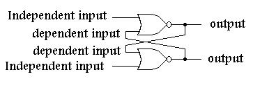
- Nand and nor flip-flops have two types of inputs, independent, tied only to the outside world, and dependent inputs, fed back from the other gate of the flip-flop.
- The truth table tells the tale:
| NOR Gate | |||||
|---|---|---|---|---|---|
| A | B | O | Comment | Comment | |
| 0 | 0 | 1 | 0 on flip-flop independent input causes either 0 or 1 out | ||
| 0 | 1 | 0 | 1 on flip-flop independent input causes 0 out | 0 on flip-flop independent input causes either 0 or 1 out | |
| 1 | 0 | 0 | 1 on flip-flop independent input causes 0 out | 0 on flip-flop independent input causes either 0 or 1 out | |
| 1 | 1 | 0 | 1 on flip-flop independent input causes 0 out | ||
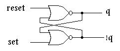
Nor Flip-Flop:
- 1 on an independent input, output of that gate will be 0.
- 0 on an independent input, output could be 0 or 1, output is dependent upon dependent input fed back from the other gate.
Looking at the truth table for a NOR gate, if a 1 appears on the independent input of a NOR gate, which is part of a NOR flip-flop, that gate's output WILL BE 0-PERIOD!
Now there is a state known as the disallowed state. The disallowed state occurs when the outputs of a flip-flop are the same state. The outputs of an R-S flip-flop are known as Q and !Q (not Q). Logically, Q cannot = !Q. Since in a NOR flip-flop, if the determinate state, 1 in this case, occurs on and an independent input the output will be in a known state, 0 in this case. If both independent inputs of a NAND gate have the determinate state, 1 in this case, on both inputs, both outputs will be 0. Remember, Q != !Q so this is a disallowed state. Stay away from it. Under a specific condition, this input state can cause the flip-flop to race. That is, when you analyze the flip-flop, you will go round and round forever with the outputs, Q and !Q, changing between 1,1 and 0,0. Like I said, stay away from the disallowed state (NOR flip-flop: 1 on both inputs)!
Now, if a 0 appears on the independent input of a NOR gate which is part of a NOR flip-flop, that gate's output may be 0 or 1 (look at the truth table), we won't know until we look at the other input which happens to be fed back from the other NOR gate of the NOR flip-flop. Therefore, if the other NOR gate of a NOR flip-flop has the determinate state, 1 in this case, 0 will be fed back from its output to the NOR gate having the indeterminate state, 0 in this case, causing the flip-flop with the indeterminate state on its input, 0 in this case, to have on its output the state opposite that on the NOR gate having the determinate state, 1 in this case.
There is one more R-S flip-flop state to talk about. It is called the no change state. If we assume that the NOR flip-flop is in the state described in the section directly above, and then change the NAND gate having the determinate state on its input to having the indeterminate state, 1 to 0 in this case, the output states will not change due to the output being fed back from the other gate. Since when the flip-flop is placed into a no change state, it is important that the flip-flop be placed into a pre-defined state before it is placed into the no change state. In other words, you must know what output states are not changing, before the circuit is analyzed.
In summary:
| NOR Flip-Flop | ||||
|---|---|---|---|---|
| S | R | Q | !Q | Comments |
| 1 | 0 | 1 | 0 | SET-Q is true, !Q is false |
| 0 | 1 | 0 | 1 | RESET-Q is false, !Q is true |
| 0 | 0 | 0 | 1 | NO CHANGE |
| 1 | 1 | X | X | DISALLOWED!!! |
Notice that in the case of the NOR flip-flop, to set Q to 1, Set sets to 1. To set !Q to 1, reset is set to 1 following the rules for the NOR gate described above.
| NAND Gate | ||||
|---|---|---|---|---|
| A | B | O | Comment | Comment |
| 0 | 0 | 1 | 0 on flip-flop independent input causes 1 out | |
| 0 | 1 | 1 | 0 on flip-flop independent input causes 1 out | 1 on flip-flop independent input causes either 0 or 1 out |
| 1 | 0 | 1 | 0 on flip-flop independent input causes 1 out | 1 on flip-flop independent input causes either 0 or 1 out |
| 1 | 1 | 0 | 1 on flip-flop independent input causes either 0 or 1 out | |
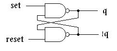
Nand Flip-Flop:
- 0 on an independent input, output of that gate will be 1.
- 1 on an independent input, output could be 0 or 1, output is dependent upon dependent input fed back from the other gate.
Looking at the truth table for a NAND gate, if a 0 appears on the independent input of a NAND gate, which is part of a NAND flip-flop, that gate's output WILL BE 1-PERIOD!
Now there is a state known as the disallowed state. The disallowed state occurs when the outputs of a flip-flop are the same state. The outputs of an R-S flip-flop are known as Q and !Q (not Q). Logically, Q cannot = !Q. Since in a NAND flip-flop, if the determinate state, 0 in this case, occurs on and an independent input the output will be in a known state, 1 in this case. If both independent inputs of a NAND gate have the determinate state, 0 in this case, on both inputs, both outputs will be 1. Remember, Q != !Q so this is a disallowed state. Stay away from it. Under a specific condition, this input state can cause the flip-flop to race. That is, when you analyze the flip-flop, you will go round and round forever with the outputs, Q and !Q, changing between 1,1 and 0,0. Like I said, stay away from the disallowed state (NAND flip-flop: 0 on both inputs)!
Now, if a 1 appears on the independent input of a NAND gate which is part of a NAND flip-flop, that gate's output may be 0 or 1 (look at the truth table), we won't know until we look at the other input which happens to be fed back from the other NAND gate of the NAND flip-flop. Therefore, if the other NAND gate of a NAND flip-flop has the determinate state, 0 in this case, 1 will be fed back from its output to the NOR gate having the indeterminate state, 1 in this case, causing the flip-flop with the indeterminate state on its input, 1 in this case, to have on its output the state opposite that on the NAND gate having the determinate state, 0 in this case.
There is one more R-S flip-flop state to talk about. It is called the no change state. If we assume that the NAND flip-flop is in the state described in the section directly above, and then change the NAND gate having the determinate state on its input to having the indeterminate state, 0 to 1 in this case, the output states will not change due to the output being fed back from the other gate. Since when the flip-flop is placed into a no change state, it is important that the flip-flop be placed into a pre-defined state before it is placed into the no change state. In other words, you must know what output states are not changing, before the circuit is analyzed.
In summary:
| NAND Flip-Flop | ||||
|---|---|---|---|---|
| S | R | Q | Q1 | Comments |
| 1 | 0 | 0 | 1 | RESET-Q is true, !Q is false |
| 0 | 1 | 1 | 0 | SET-Q is false, !Q is true |
| 1 | 1 | 1 | 0 | NO CHANGE |
| 0 | 0 | X | X | DISALLOWED!!! |
Notice that in the case of the NAND flip-flop, to set Q to 1, Set set to 0. To set !Q to 1, reset is set to 0 following the rules for the NAND gate described above.
- Stay away from the disallowed state-PERIOD!
- When analyzing a flip-flop, put it in an definite state (not the no change state-this rule can be broken, see note at the end!).
- There are only two valid states on the output of an R-S flip-flop, either 0, 1 or 1, 0
- There are only three valid states on the input of an R-S flip-flop: 0,1 or 1,0, or no change (see flip-flop truth tables)
Note: this rule can be broken. That is, you can start with the flip-flop in the no-change (input) state AS LONG AS you assign the outputs to either 0,1 or 1,0 and then analyze the flip-flop. By assigning states to the outputs, however, you are simply defining the previous state so you could do this by manipulating inputs and then observing the outputs BEFORE changing to the no change state.


