Table of Contents
BACKGROUND
For this project we will be building off the previous project vcc0 and integrating a button into our circuit to allow the circuit to count up without input from the button and count backward while pressing the button.
BITWISE LOGIC OPERATORS
There are six bitwise logic operators. These operators work at bit-level and deal with the binary forms of numbers:
- & (bitwise AND) will compare each bit of two operands and give a result of 1 in that position if both operands have a 1 in that position.
- | (bitwise OR) will compare each bit of two operands and give a result of 1 in that position if either operand have a 1 in that position.
- ^ (bitwise XOR) will compare each bit of two operands and return a 1 in that position if one operand has a 1 in that position but the other does not
- « (left shift) will shift each bit of the first operand to the left by an amount equal to the second operand
- » (right shift) will shift each bit of the first operand to the right by an amount equal to the second operand
- ~ (bitwise NOT) will invert each bit of an operand.
To show these, let's take the numbers 60 (0011 1100) and 90 (0101 1010):
- x = 60 & 90 results in x = 24 (0001 1000)
- x = 60 | 90 results in x = 126 (0111 1110)
- x = 60 ^ 90 results in x = 102 (0110 0110)
- x = 60 « 2 results in x = 240 (1111 0000)
- x = 60 » 2 results in x = 15 (0000 1111)
- x = ~60 results in x = 195 (1100 0011)
ELECTRONICS
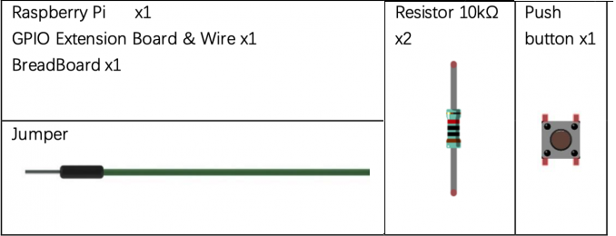
PARTS
BUTTON
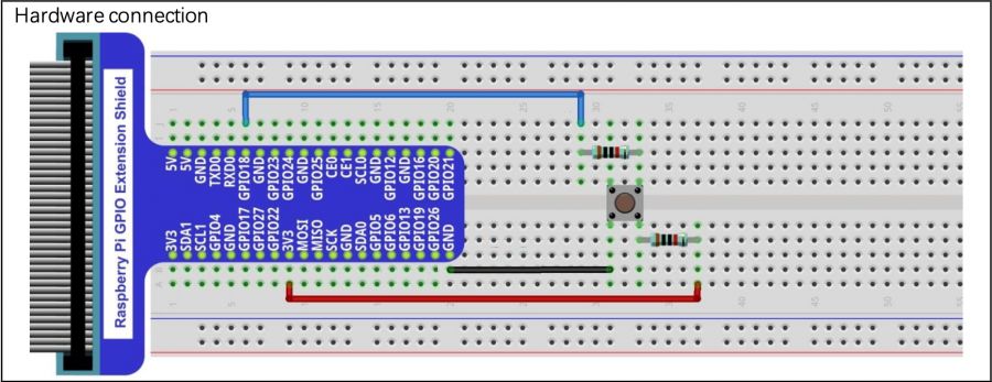
Here is a diagram for hooking up a button:
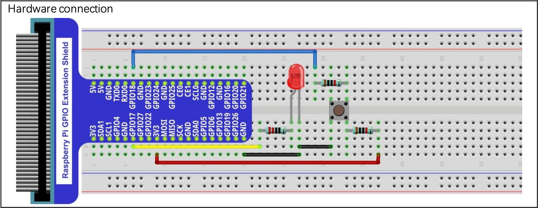
A possible manual test with an LED:
The main function of the button is to change the direction of the counting of the LED lights. In vcc1, like vcc0, you program the LED lights to count up to a certain number. In the vcc1, the LED lights count up to 64, and by pressing the button, the LED lights will count backwards from 63.
PROGRAM
The sample program in the project grabit will have the basic necessities to start off your program.
First step will be to change the definition (pin #) of your button.
Replace “num” with the wiringpi pin number of the GPIO for your button
#define BUTTON num
Now we have to set the number of LED's that we are connecting to our Pi to specify the size of our pin array.
Enter the number of LED's you are using, in the case of this project 6
#define NUM_LEDS 6
Next, we define our variables. The sample program already defines both our index int value as well as declaring our pin array for pin assignments. If you would like to define a different variable for your counter or for any other necessary variables, do it here.
Int container = 0; num_container = 32;
Now we have to set up our pin array. Much like the last project, you're assigning each pin an array assignment (0-6) within the array, then defining what Wiringpi pin it corresponds to. Remember to set your pin for your button as an input and your led pins as outputs.
Using
gpio readall
in your terminal can help you find both the BCM number and the corresponding wiringpi numbers.


