User Tools
Sidebar
This is an old revision of the document!
Table of Contents
BACKGROUND
SELECTION LOGIC
RELATIONAL OPERATORS
| Operator |
|---|
| == |
| != |
| > |
| < |
| >= |
| ⇐ |
WIRINGPI INSTALL
In order to navigate successfully throughout the wiringPi library in the command-line, a few key functions are going to be needed:
gpio readall: This allows view of the table that correlates to the pins and positions on the breadboard. It gives the pin number in terms of what the Pi reads and in terms of what code for the project reads. It allows tells whether the pin is in Input mode or Output mode.
gpio mode: This allows one to change the mode of specific pins from Input to Output and visa versa. Once the command is typed, it will ask for the desired pin number (found in the readall table) and the desired mode (In/Out).
gpio write: Once the desired pins have been hooked up on the breadboard and configured on the Pi, this function is used to switch between supplying voltage or not. Once typed, it will ask for the desired pin (which should already be configured) and a choice of 0(off) and 1(on).
ELECTRONICS
BREADBOARD
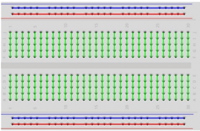
The breadboard is the device we will use to build our circuits:
The electrical layout of the breadboard is as follows:
Here's a good video overview of the functionality of a breadboard:
COMPONENTS
A breadboard consists of plastic block holding a matrix of electrical sockets of a size suitable for gripping thin connecting wire, component wires or the pins of transistors and integrated circuits. The sockets are connected inside the board, usually in rows of five sockets.
CIRCUIT
ONE LED
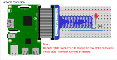
Here is a diagram for a circuit driving one LED, from one GPIO pin:
You are after a circuit that drives four LEDs, each one from a unique GPIO pin.
FOUR LED
You will want to identify 2 additional GPIO pins (The example program has BCM 17 and 18 already included to run as an output) and you can identify the wiringpi pin number/BCM number by using
yourpi:~$ gpio readall
This will give you what your machine has for GPIO's, what the BCM Pin number is, as well as what the wiringpi pin number is. Each LED will require a GPIO power jumper wire, a resistor, and a ground. You can either use a different ground pin for each or simply use one ground pin ran to the ground rail on either side of the breadboard then ground all LEDs to the ground rail. Arranging your LEDs in a straight line of 4 is ideal as you will have each binary digit represented in order from right to left.
SPECIFICATIONS
PI SETUP
NOTE: As of 20220908, is not working for the pi 400. See the section below for the pi 400 workaround.
First, we need to download the wiringPi library package:
yourpi:~$ wget https://project-downloads.drogon.net/wiringpi-latest.deb
Then, we need to install it:
yourpi:~$ sudo dpkg -i wiringpi-latest.deb
wiringPi on the pi400
For the pi400, we have to do a slightly different process, but will result in the needed functionality becoming available.
On the pi (doesn't matter where, although probably NOT in your repository; base of home directory works fine):
yourpi~$ git clone https://github.com/WiringPi/WiringPi.git
Then:
yourpi:~$ cd WiringPi
yourpi:~/WiringPi$
Finally, build and install it:
yourpi:~/WiringPi$ ./build
Provided there are no apparent errors, close out of that terminal and open a new one, then the gpio tool and related WiringPi functionality should now be available.


