User Tools

Site Tools


Sidebar

projects

ntr0 (due 20210825)
pct1 (bonus; due 20210819)
wcp1 (due 20210818)
pct2 (due 20210825)
wcp2 (due 20210825)
lob0 (due 20210901)
pct3 (bonus; due 20210901)
wcp3 (due 20210901)
led0 (due 20210908)
pct4 (due 20210908)
wcp4 (due 20210908)
led1 (due 20210915)
gfo0 (due 20210915)
pct5 (bonus; due 20210915)
wcp5 (due 20210915)
led2 (due 20210922)
pct6 (due 20210922)
wcp6 (due 20210922)
iwb0 (due 20210929)
pct7 (bonus; due 20210929)
wcp7 (due 20210929)
iwb1 (due 20211006)
pct8 (due 20211006)
wcp8 (due 20211006)
iwb2 (due 20211020)
pct9 (bonus; due 20211020)
bwp1 (bonus; due 20211020)
wcp9 (due 20211020)
clr0 (due 20211027)
gfo1 (due 20211027)
pctA (due 20211027)
wcpA (due 20211027)
clr1 (due 20211103)
pctB (bonus; due 20211103)
wcpB (due 20211103)
clr2 (due 20211110)
pctC (due 20211110)
wcpC (due 20211110)
gfo2 (due 20211117)
pctD (bonus; due 20211117)
pctE (bonus; due 20211201)
bwp2 (bonus; due 20211201)
EoCE (due 20211209)
haas:fall2021:c4eng:projects:iwb2

Corning Community College

ENGR1050 C for Engineers

PROJECT

PROJECT: Input With Buttons (iwb2)

Objective

In the ledX electronics projects, we played exclusively with output components, in the form of LEDs. Here, we continue our use of buttons, further enhancing the functionality of the input and resulting sophistication in the control of the overall process.

Here we put it all together: maximal button and LED goodness!

Abstraction

As an exercise in toning your abstraction abilities (literally seeing one thing, but understanding and using it as something else), there will be a number of 'generic' terms used throughout this (and other) documents throughout the course, requiring you to substitute in the pertinent information (else face confusion or error).

Some examples:

  • yourusername - where you see this (likely in a config file or command-line argument), you are NOT to literally type in y-o-u-r-u-s-e-r-n-a-m-e, but instead, substitute in YOUR lab46 username.
  • desig - different classes have different class designations. To make one universal document pertinent to ALL classes, specific examples will instead use 'desig', where you must substitute in the class desig of the class YOU are taking and acting upon in that moment. Example class desigs:
    • c4eng - ENGR1050 “C for Engineers”
    • cprog - CSCS1320 “C/C++ Programming”
    • unix - CSCS1730 “UNIX/Linux Fundamentals”
    • data - CSCS2320 “Data Structures”
    • discrete - CSCS2330 “Discrete Structures”
    • comporg - CSCS2650 “Computer Organization”
    • sysprog - CSCS2730 “Systems Programming”

This sort of abstraction is very similar to that we will find in our utilization of variables in programming, where we can have a “name”, but the data associated with it can change based on various conditions.

Do not be a literalist computer! Start to exercise your abstraction abilities.

2021/08/01 10:37

Locational Awareness

This document is written with TWO locations in mind:

  • lab46 (the system you may retrieve resources and SUBMIT projects)
    • identified in examples with the use of the lab46:~$ prompt
  • your pi (the system you will transfer resources to/from, and WORK ON/COMPLETE projects)
    • identified in examples with the use of the yourpi:~$ prompt

There are commands you can ONLY run on one system or the other. Pay attention to any prompt cues in the given examples (or section headings, context of language leading up to any examples).

For example:

  • YOU cannot install software on lab46. You don't have access.
  • projects CANNOT be SUBMITTED on your pi.

Please pay attention to your prompt, so you can perform the needed activity on the correct system.

2021/08/01 10:37

Reading

Please be sure to familiarize yourself with the following content in “the C book”:

Background

For this project, you will be working with a C program using the wiringPi library on the Raspberry Pi, wiring up a circuit containing multiple LEDs and a button to your breadboard and witnessing your ability to access and control them via software.

Input and Output via the GPIO pins on the pi

One of the intended uses of the Raspberry Pi and other small, single board computers is as an interface tool to peripherals in projects, personal and industrial.

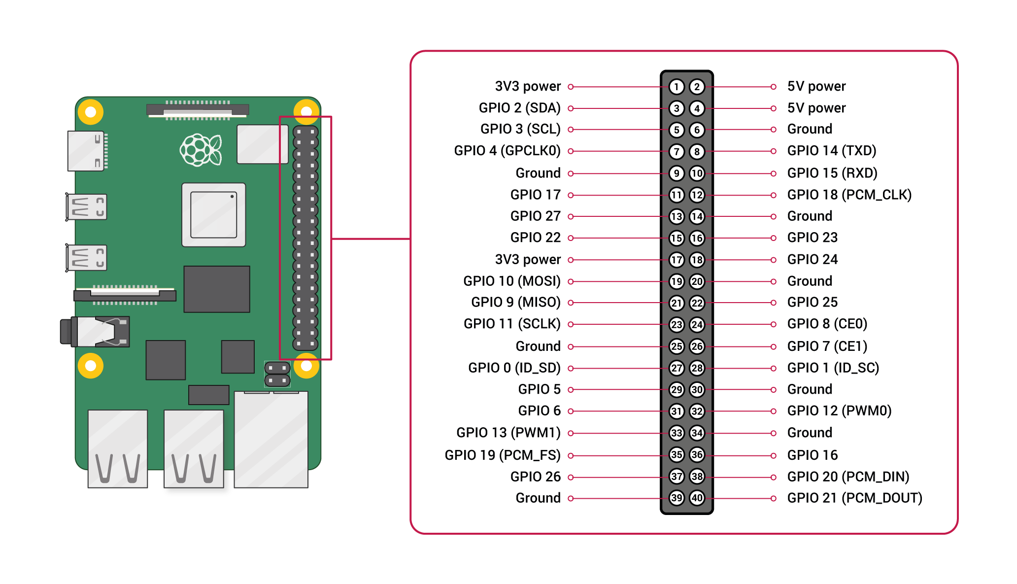
The pi has a set of General Purpose Input Output (GPIO) pins intended for precisely this purpose:

Please note the orientation of the pi (ethernet/USB at bottom) to calibrate yourself to the location of pin 1 and all subsequent pins, along with their identified function (ie top left pin, pin 1, provides a constant 3.3v DC power)

We can also get a live update on the state of each pin on our pi itself, using the 'gpio readall' command at our pi prompt:

yourpi:~/src/SEMESTER/DESIG/iwb2$ gpio readall
 +-----+-----+---------+------+---+---Pi 4B--+---+------+---------+-----+-----+
 | BCM | wPi |   Name  | Mode | V | Physical | V | Mode | Name    | wPi | BCM |
 +-----+-----+---------+------+---+----++----+---+------+---------+-----+-----+
 |     |     |    3.3v |      |   |  1 || 2  |   |      | 5v      |     |     |
 |   2 |   8 |   SDA.1 | ALT0 | 1 |  3 || 4  |   |      | 5v      |     |     |
 |   3 |   9 |   SCL.1 | ALT0 | 1 |  5 || 6  |   |      | 0v      |     |     |
 |   4 |   7 | GPIO. 7 |   IN | 0 |  7 || 8  | 1 | ALT5 | TxD     | 15  | 14  |
 |     |     |      0v |      |   |  9 || 10 | 1 | ALT5 | RxD     | 16  | 15  |
 |  17 |   0 | GPIO. 0 |   IN | 0 | 11 || 12 | 0 | IN   | GPIO. 1 | 1   | 18  |
 |  27 |   2 | GPIO. 2 |   IN | 0 | 13 || 14 |   |      | 0v      |     |     |
 |  22 |   3 | GPIO. 3 |   IN | 0 | 15 || 16 | 0 | IN   | GPIO. 4 | 4   | 23  |
 |     |     |    3.3v |      |   | 17 || 18 | 0 | IN   | GPIO. 5 | 5   | 24  |
 |  10 |  12 |    MOSI |   IN | 0 | 19 || 20 |   |      | 0v      |     |     |
 |   9 |  13 |    MISO |   IN | 0 | 21 || 22 | 0 | IN   | GPIO. 6 | 6   | 25  |
 |  11 |  14 |    SCLK |   IN | 0 | 23 || 24 | 1 | IN   | CE0     | 10  | 8   |
 |     |     |      0v |      |   | 25 || 26 | 1 | IN   | CE1     | 11  | 7   |
 |   0 |  30 |   SDA.0 |   IN | 1 | 27 || 28 | 1 | IN   | SCL.0   | 31  | 1   |
 |   5 |  21 | GPIO.21 |   IN | 1 | 29 || 30 |   |      | 0v      |     |     |
 |   6 |  22 | GPIO.22 |   IN | 1 | 31 || 32 | 0 | IN   | GPIO.26 | 26  | 12  |
 |  13 |  23 | GPIO.23 |   IN | 0 | 33 || 34 |   |      | 0v      |     |     |
 |  19 |  24 | GPIO.24 |   IN | 0 | 35 || 36 | 0 | IN   | GPIO.27 | 27  | 16  |
 |  26 |  25 | GPIO.25 |   IN | 0 | 37 || 38 | 0 | IN   | GPIO.28 | 28  | 20  |
 |     |     |      0v |      |   | 39 || 40 | 0 | IN   | GPIO.29 | 29  | 21  |
 +-----+-----+---------+------+---+----++----+---+------+---------+-----+-----+
 | BCM | wPi |   Name  | Mode | V | Physical | V | Mode | Name    | wPi | BCM |
 +-----+-----+---------+------+---+---Pi 4B--+---+------+---------+-----+-----+

Yes, it may be packed with information, but it is an informative, technical reference.

Why is this so layered and directed, you may ask? Well, it is a matter of competing standards (approaches to identification of each pin, based on particular reference points).

For example, the “Physical” columns (dead center) in the center conform to the image diagram I posted above of the 40 pins (where pin 1 is the top-left).

The “BCM” columns (far left and far right) refer to the hardware identifications for each pin by the manufacturer. You might notice that BCM pin 17 (physical pin 11) corresponds to wPi pin 0.

And the “wPi” columns (second from left, and second from right), correspond to the pin identifications as use by the wiringPi library, which we are using here.

Additionally, we see “Mode” and “V” columns; mode informs us of the operating mode of that pin at present configuration (IN means it is configured for INPUT, OUT means it is configured for OUTPUT). V implies voltage on the pin (0 means no voltage, 1 means there is voltage present at time of checking). For this project, we will be configuring a specific pin to OUTPUT mode, and modulating it between a state of ON (1) and OFF (0).

So, in exploring the use of the table: if we wanted to hook a component up to wiringPi pin #0, that corresponds to manufacturer (BCM) pin 17, which is physical pin 11.

You will want to verify placement before supplying power, that is why we are taking things slow, and providing you opportunities to confirm (by posting pictures in the discord channel) before proceeding.

It may seem a bit bewildering or overwhelming at first, but like anything, time and exposure will ensure it becomes increasingly second nature.

Wiring up our circuit

This circuit is basically an enhancement upon the one you made for the led1 project. So the parts needed has some similar items, but also some new ones.

In this project, we will be hooking up two different peripherals to some of our Raspberry Pi pins: a set of light emitting diodes (LED) and a button, and then proceed to interface with them to access and control their state (of being ON or OFF).

You have likely encountered LEDs endlessly in your everyday life: commonly used as a “power light”, which when lit, indicates the device is powered on, among many, MANY, MANY other applications.

You have also encountered buttons seemingly in just as ubiquitous a fashion: a button is essentially a switch, toggling something ON or OFF. A light switch is a prime example of this (although in our case, our button doesn't remain in the changed state- once we release it, like a keyboard key, it reverts to its default state).

For this endeavour, you will need to obtain the following items out of the electronics kit you obtained for the class:

The Circuit to Construct

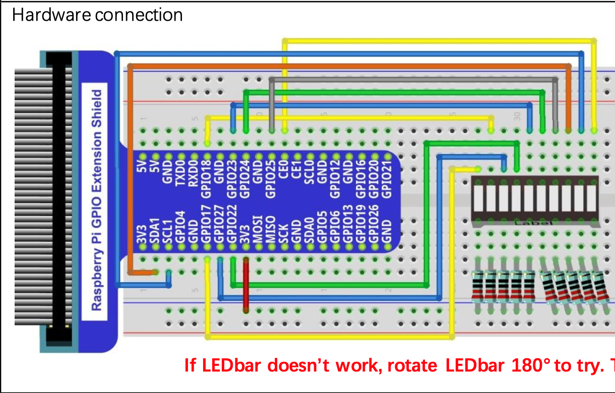
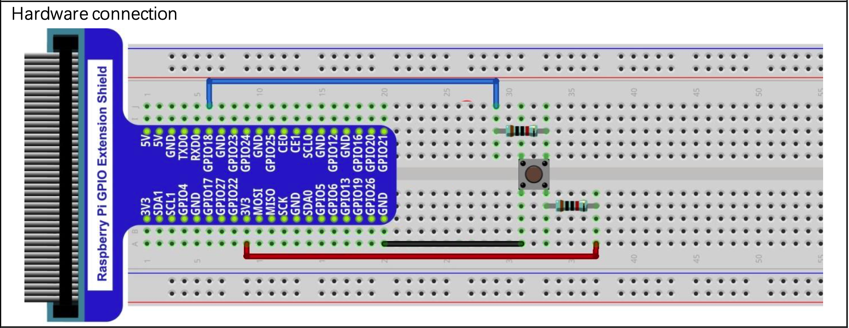
With those components, you will want to place them onto your breadboard, in a manner similar to previous week's circuits (namely, a combination of led2 and iwb1), but obviously with something different going on.

Of particular note: we are going to create circuit involving TWO buttons, and the LEDbar we last used in the led2 project. Each button will perform a unique function, impacting what gets displayed on the LEDbar.

Included here again is the led2 circuit, for reference:

And an isolated button circuit:

You want to COMBINE the two circuits, without any overlap or conflicted use of GPIO pins. The idea is for you to study the two circuits in isolation, develop an understanding, and then integrate both into the same super-circuit.

Take note of how everything is being plugged in, and what connection on the T-cobbler is being utilized.

Pay attention to the color bands of the resistors! We are using two different kinds on this project, and mixing them up will result in erratic or nonfunctional results!

Before you seek to actually test your circuit, please get verification to proceed from the class channel on discord by posting a clear picture of everything (a focus on a clear view of the wires, and where they plug into the breadboard). There are MANY parts, and especially as we have our first exposure, it is best to insert as many quality control checks as possible to ensure the greatest chances of mistakes are mitigated.

Program

It is your task to implement a program (iwb2.c) that accepts input from the buttons, and outputs to the LEDbar, in accordance with the following:

  • the LEDbar displays a 10-bit binary number (you were to write code in previous projects that accomplishes this task)
  • ONE of the two buttons is an NONE/INCREMENT/DECREMENT toggle.
    • By pressing it, your program needs to recognize it is pressed, and adjust the mode accordingly:
      • if in NONE, switch to INCREMENT
      • if in INCREMENT, switch to DECREMENT
      • if in DECREMENT, switch to NONE
  • the OTHER of the two buttons is a SPEED (100-1000mS, changing in quantities of 100) adjustment.
    • By pressing it, your program needs to recognize it is pressed, and adjust the speed accordingly:
      • increment your delay by 100mS (from whatever it is currently set to)
      • when you reach 1000 and continue to adjust the speed, it should wrap around to 100.
  • some things of note:
    • each LED connected to a unique GPIO line
    • each BUTTON connected to a unique GPIO line

Grabbing project resources (on lab46)

I have prepared a grabit for resources related to this project. To obtain:

lab46:~/src/SEMESTER/DESIG$ grabit DESIG iwb2
make: Entering directory '/var/public/SEMESTER/DESIG/iwb2'
'/var/public/SEMESTER/DESIG/iwb2/Makefile' -> '/home/user/src/SEMESTER/DESIG/iwb2/Makefile'
'/var/public/SEMESTER/DESIG/iwb2/iwb2.c' -> '/home/user/src/SEMESTER/DESIG/iwb2/iwb2.c'
make: Leaving directory '/var/public/SEMESTER/DESIG/iwb2'
lab46:~/src/SEMESTER/DESIG$ 

At which point you can change into the newly created and populated iwb2/ directory.

Getting project resources from lab46 to your pi

Okay, you've snagged the project files on lab46. Now, how to get them to your pi?

The same way you've been juggling project files already, by using your mercurial repository!

Using the hg tool, be sure to add, commit, and push successfully on lab46.

Then, over on your pi, use hg to pull and update the new changes into place. Then you can proceed.

On your pi

Study and run this program on your pi in conjunction with testing and verifying operation of your properly hooked up electronics circuit. When done, submit it on lab46.

To utilize the needed functionality for this project, you will need to ensure you have the following packages installed:

  • build-essential (hopefully you took care of this in ntr0)
  • wiringpi (hopefully you took care of this in led0)

Compiling

Since the grabit brought in a Makefile, you can compile your code simply by typing: make

Any compiler errors will go into a text file called errors

To do a full cleaning, run: make clean then make (or make debug)

If you'd like to see compiler messages as you compile, run: make debug

When done and ready to submit, on lab46: make submit

Submission

To successfully complete this project, the following criteria must be met:

  • Code must compile cleanly (no notes, warnings, nor errors)
  • Output must be correct, and match the form given in the sample output above.
  • Code must be nicely and consistently indented
  • Code must be well commented
  • Do NOT double space your code. Group like statements together.
  • Output Formatting (including spacing) of program must conform to the provided output (see above).
  • Track/version the source code in a repository
  • Submit a copy of your source code to me using the submit tool.
  • Post required images and obtain needed confirmation to proceed from me on class channel on discord.

To submit this program to me using the submit tool, run the following command at your lab46 prompt:

lab46:~/src/SEMESTER/DESIG/iwb2$ make submit

You should get some sort of confirmation indicating successful submission if all went according to plan. If not, check for typos and or locational mismatches.

What I'll be looking for:

78:iwb2:final tally of results (78/78)
*:iwb2:post picture of unpowered layout to #desig and get approval [8/8]
*:iwb2:post picture to #desig by Sunday before deadline [4/4]
*:iwb2:post picture of powered LEDs in layout to #desig [8/8] 
*:iwb2:grabit on the code on lab46 by Sunday before deadline [4/4]
*:iwb2:iwb2.c code adequately modified per project requirements [32/32]
*:iwb2:iwb2.c comments describing what is happening [12/12]
*:iwb2:updated code is pushed to lab46 repository [10/10]

Additionally:

  • Solutions not abiding by spirit of project will be subject to a 25% overall deduction
  • Solutions not utilizing descriptive why and how comments will be subject to a 25% overall deduction
  • Solutions not utilizing indentation to promote scope and clarity will be subject to a 25% overall deduction
  • Solutions not organized and easy to read are subject to a 25% overall deduction
2021/08/09 10:37
haas/fall2021/c4eng/projects/iwb2.txt · Last modified: 2021/10/03 16:35 by 127.0.0.1