Table of Contents
<html><center></html>Computer Organization Course Notes wiki<html></center></html>
Who is doing what
- afassett - Fixing bugs/whatever the hell Anthony wants
- Steve - currently working on 6502 instructions set and alg's (MOS 6502 address and instruction adds)
- Thatch - Logic functions, and buying dinner for the whole class on Monday afternoon!
- bholl695 - full adder
- Jr018429 - memory in alu for 8085
- nate - half adder
- justin - directory structure (and some code)other various register circuits
- AndMore - Constructing and cleaning the 8085 CPU. Data Transfer is basically done. moving to logic or branch next. Building the interpreter for the 8085 (completed almost through arithmetic selection.) Searching for the rosetta stone to assembly intake. (Thatch wasn't in the lab on Monday!)
- sweller5 - NAND flip-flop / Coordinator / supreme ruler of the universe.
- jhammo13 - Documentation
Please please e-mail the class mailing list on what your working on and update this page so that we all can see and know what your working on Thanks.
WHO working on what
Please add your self to the list of what CPU you would like to work on Thanks. Both CPU's have a web page please put the documentation there for them Thank you.
TODO
A scratch space of ideas/tasks that need attention with respect to the project. Feel free to add items, and be sure to remove completed items.
- submenu categories
- submenu options
- command-line arguments
- General functions for logical operations.
- Individual action specific functions for Logical OpCodes.
Things that compile but need editing to work(bugs/incomplete)
- fulladder
- hadder
- ffnand
- the LHLD and SHLD functions in the 8085 register class need addition which will incriment the second half of the address btw put 1 and put 2.
Other(in progress)
- shift register (same but with ability to “shift” bits) - shift function (with bit retention) is available in the 8085 register class.
- adder circuit (be able to “add” two registers together)
- subtractor circuit (“subtract” two registers)
- negation circuit (inverts a register)
- copy circuit (copies a register) - available using the move functions found in the 8085 register class.
- Hex Code translation for individual OPcodes. (There's a list of them with translation on the 8085 page.)
R-S Flip-Flop Tutorial
by John Rine
Because a few people in the class said “flip-flops make my brain hurt” (my paraphrase), I thought I would add a tutorial that might help people understand and appreciate them.
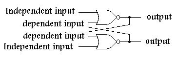
- Nand and nor flip-flops have two types of inputs, independent, tied only to the outside world, and dependent inputs, fed back from the other gate of the flip-flop.
- The truth table tells the tale:
| NOR Gate | |||||
|---|---|---|---|---|---|
| A | B | O | Comment | Comment | |
| 0 | 0 | 1 | 0 on flip-flop independent input causes either 0 or 1 out | ||
| 0 | 1 | 0 | 1 on flip-flop independent input causes 0 out | 0 on flip-flop independent input causes either 0 or 1 out | |
| 1 | 0 | 0 | 1 on flip-flop independent input causes 0 out | 0 on flip-flop independent input causes either 0 or 1 out | |
| 1 | 1 | 0 | 1 on flip-flop independent input causes 0 out | ||
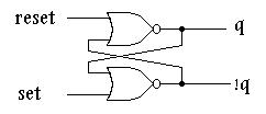
Nor Flip-Flop:
- 1 on an independent input, output of that gate will be 0.
- 0 on an independent input, output could be 0 or 1, output is dependent upon dependent input fed back from the other gate.
Looking at the truth table for a NOR gate, if a 1 appears on the independent input of a NOR gate, which is part of a NOR flip-flop, that gate's output WILL BE 0-PERIOD!
Now there is a state known as the disallowed state. The disallowed state occurs when the outputs of a flip-flop are the same state. The outputs of an R-S flip-flop are known as Q and !Q (not Q). Logically, Q cannot = !Q. Since in a NOR flip-flop, if the determinate state, 1 in this case, occurs on and an independent input the output will be in a known state, 0 in this case. If both independent inputs of a NAND gate have the determinate state, 1 in this case, on both inputs, both outputs will be 0. Remember, Q != !Q so this is a disallowed state. Stay away from it. Under a specific condition, this input state can cause the flip-flop to race. That is, when you analyze the flip-flop, you will go round and round forever with the outputs, Q and !Q, changing between 1,1 and 0,0. Like I said, stay away from the disallowed state (NOR flip-flop: 1 on both inputs)!
Now, if a 0 appears on the independent input of a NOR gate which is part of a NOR flip-flop, that gate's output may be 0 or 1 (look at the truth table), we won't know until we look at the other input which happens to be fed back from the other NOR gate of the NOR flip-flop. Therefore, if the other NOR gate of a NOR flip-flop has the determinate state, 1 in this case, 0 will be fed back from its output to the NOR gate having the indeterminate state, 0 in this case, causing the flip-flop with the indeterminate state on its input, 0 in this case, to have on its output the state opposite that on the NOR gate having the determinate state, 1 in this case.
There is one more R-S flip-flop state to talk about. It is called the no change state. If we assume that the NOR flip-flop is in the state described in the section directly above, and then change the NAND gate having the determinate state on its input to having the indeterminate state, 1 to 0 in this case, the output states will not change due to the output being fed back from the other gate. Since when the flip-flop is placed into a no change state, it is important that the flip-flop be placed into a pre-defined state before it is placed into the no change state. In other words, you must know what output states are not changing, before the circuit is analyzed.
In summary:
| NOR Flip-Flop | ||||
|---|---|---|---|---|
| S | R | Q | !Q | Comments |
| 1 | 0 | 1 | 0 | SET-Q is true, !Q is false |
| 0 | 1 | 0 | 1 | RESET-Q is false, !Q is true |
| 0 | 0 | 0 | 1 | NO CHANGE |
| 1 | 1 | X | X | DISALLOWED!!! |
Notice that in the case of the NOR flip-flop, to set Q to 1, Set sets to 1. To set !Q to 1, reset is set to 1 following the rules for the NOR gate described above.
| NAND Gate | ||||
|---|---|---|---|---|
| A | B | O | Comment | Comment |
| 0 | 0 | 1 | 0 on flip-flop independent input causes 1 out | |
| 0 | 1 | 1 | 0 on flip-flop independent input causes 1 out | 1 on flip-flop independent input causes either 0 or 1 out |
| 1 | 0 | 1 | 0 on flip-flop independent input causes 1 out | 1 on flip-flop independent input causes either 0 or 1 out |
| 1 | 1 | 0 | 1 on flip-flop independent input causes either 0 or 1 out | |
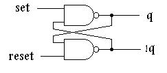
Nand Flip-Flop:
- 0 on an independent input, output of that gate will be 1.
- 1 on an independent input, output could be 0 or 1, output is dependent upon dependent input fed back from the other gate.
Looking at the truth table for a NAND gate, if a 0 appears on the independent input of a NAND gate, which is part of a NAND flip-flop, that gate's output WILL BE 1-PERIOD!
Now there is a state known as the disallowed state. The disallowed state occurs when the outputs of a flip-flop are the same state. The outputs of an R-S flip-flop are known as Q and !Q (not Q). Logically, Q cannot = !Q. Since in a NAND flip-flop, if the determinate state, 0 in this case, occurs on and an independent input the output will be in a known state, 1 in this case. If both independent inputs of a NAND gate have the determinate state, 0 in this case, on both inputs, both outputs will be 1. Remember, Q != !Q so this is a disallowed state. Stay away from it. Under a specific condition, this input state can cause the flip-flop to race. That is, when you analyze the flip-flop, you will go round and round forever with the outputs, Q and !Q, changing between 1,1 and 0,0. Like I said, stay away from the disallowed state (NAND flip-flop: 0 on both inputs)!
Now, if a 1 appears on the independent input of a NAND gate which is part of a NAND flip-flop, that gate's output may be 0 or 1 (look at the truth table), we won't know until we look at the other input which happens to be fed back from the other NAND gate of the NAND flip-flop. Therefore, if the other NAND gate of a NAND flip-flop has the determinate state, 0 in this case, 1 will be fed back from its output to the NOR gate having the indeterminate state, 1 in this case, causing the flip-flop with the indeterminate state on its input, 1 in this case, to have on its output the state opposite that on the NAND gate having the determinate state, 0 in this case.
There is one more R-S flip-flop state to talk about. It is called the no change state. If we assume that the NAND flip-flop is in the state described in the section directly above, and then change the NAND gate having the determinate state on its input to having the indeterminate state, 0 to 1 in this case, the output states will not change due to the output being fed back from the other gate. Since when the flip-flop is placed into a no change state, it is important that the flip-flop be placed into a pre-defined state before it is placed into the no change state. In other words, you must know what output states are not changing, before the circuit is analyzed.
In summary:
| NAND Flip-Flop | ||||
|---|---|---|---|---|
| S | R | Q | Q1 | Comments |
| 1 | 0 | 0 | 1 | RESET-Q is true, !Q is false |
| 0 | 1 | 1 | 0 | SET-Q is false, !Q is true |
| 1 | 1 | 1 | 0 | NO CHANGE |
| 0 | 0 | X | X | DISALLOWED!!! |
Notice that in the case of the NAND flip-flop, to set Q to 1, Set set to 0. To set !Q to 1, reset is set to 0 following the rules for the NAND gate described above.
- Stay away from the disallowed state-PERIOD!
- When analyzing a flip-flop, put it in an definite state (not the no change state-this rule can be broken, see note at the end!).
- There are only two valid states on the output of an R-S flip-flop, either 0, 1 or 1, 0
- There are only three valid states on the input of an R-S flip-flop: 0,1 or 1,0, or no change (see flip-flop truth tables)
Note: this rule can be broken. That is, you can start with the flip-flop in the no-change (input) state AS LONG AS you assign the outputs to either 0,1 or 1,0 and then analyze the flip-flop. By assigning states to the outputs, however, you are simply defining the previous state so you could do this by manipulating inputs and then observing the outputs BEFORE changing to the no change state.
A Basic Boolean Operations Class
I wrote a very simple class, booleanOps, for Boolean operations. As of today (Thursday, January 27), it is located in the Subversion repository. Its file name is booleanOperators.cpp. Please look at the file; besides a very simple class, it also contains a program which creates an instance of the class in order to check the and & or functions.
-John Rine 01/27/2011
Individual gates have been separated and relocated into their own individual sub-directories. Each gate has been assigned it's own class with set functions for one or two inputs, and reset functions, along with get functions. The boolOps directory now includes AND, NAND, NOR, NOT, OR, and XOR directories.
Header files for the individual logic gate classes and compilations are located in the ~/src/cpu/include/ directory.
With working logic gates coded we can now begin to combine them to create more complex circuits. Combining and interconnecting two NOR gates gives us the implementation of the first flip-flop. It has been coded checked added and submitted in the ~/src/cpu/flipflop/ directory. We now have a basic logic circuit which would hold it's state when external inputs are 0. This is the basic memory building block.
Directory Tree
| Directory | File | Description | API Location |
|---|---|---|---|
| ./ | . | Base of CPU project source tree | |
| ./ | README | Information regarding our project implementation | |
| ./ | main.cc | start of an ASCII prompt interface for the simulator | |
| ./boolOps | . | Base of Boolean Operator class directories | |
| ./boolOps | Makefile | Makefile to build the archieve for all boolops | |
| ./boolOps/and | . | AND gate code | AND API |
| ./boolOps/and | Makefile | Makefile for automated building | |
| ./boolOps/and | and.cc | AND gate class implementation | |
| ./boolOps/and | andtest.cc | AND gate class test application | |
| ./boolOps/or | . | OR gate code | OR API |
| ./boolOps/or | Makefile | Makefile for automated building | |
| ./boolOps/or | or.cc | OR gate class implementation | |
| ./boolOps/or | ortest.cc | OR gate class test application | |
| ./boolOps/xor | . | XOR gate code | XOR API |
| ./boolOps/xor | Makefile | Makefile for automated building | |
| ./boolOps/xor | xor.cc | XOR gate class implementation | |
| ./boolOps/xor | xortest.cc | XOR gate class test application | |
| ./boolOps/not | . | NOT gate code | NOT API |
| ./boolOps/not | Makefile | Makefile for automated building | |
| ./boolOps/not | not.cc | NOT gate class implementation | |
| ./boolOps/not | nottest.cc | NOT gate class test application | |
| ./boolOps/nand | . | NAND gate code | NAND API |
| ./boolOps/nand | nand.cc | NAND gate class implementation | |
| ./boolOps/nor | . | NOR gate code | |
| ./boolOps/nor | nor.cc | NOR gate class implementation | |
| ./boolops/hadder | hadder | Half Adder Class Implemenation | |
| ./boolops/fadder | fadder.cc | Full Adder class Implementation | |
| ./boolops/fullAdder2 | fullAdder2.cc | Full Adder Class Implementation | Full Adder API |
| ./include | . | Gate Headerfile code | |
| ./include | and.h | AND gate header file | |
| ./include | ffnor.h | NOR Flip-Flop header file | |
| ./include | nand.h | NAND gate header file | |
| ./include | nor.h | NOR gate header file | |
| ./include | not.h | NOT gate header file | |
| ./include | or.h | OR gate header file | |
| ./include | xnor.h | XNOR gate header file | |
| ./include | xor.h | XOR gate header file | |
| ./include | cpumem.h | CPU memory header file | |
| ./include | alu.h | alu header file | |
| ./flipflop | Base of Flip Flop Gate-combination directories | ||
| ./flipflop/ffnor | . | NOR Flip Flop code | |
| ./flipflop/ffnor | ffnor.cc | NOR Flip-Flop class implementation | |
| ./flopflop/g8sr | . | . | |
| ./flipflop/g8sr | g8sr.cc | g8sr code | |
| ./flipflop/ffnand | . | . | |
| ./cpumemory | Base of memory files | CPUMEM API | |
| ./cpumemory | Makefile | ||
| ./cpumemory | cpumem.cc | ||
| ./cpumemory | memtest.cc | ||
| ./6502 | . | . | |
| ./6502 | Makefile | Makefile that complies the 6502 cpu. Going to makefiles for Rgister, ALU | |
| ./6502 | interpreter.cc | Takes Hex input and carries out the opperation | |
| ./6502 | register | Makes the 6 registers for the 6502 | |
| ./6502/register | register.cc | The .cc file for 6502 | |
| ./6502 | opcodes | Instruction codes in HEX functions separated into .cc files | |
| ./6502 | memory | The API for 6502's memory | |
| ./8085/arithmeticlogicunit | Base of alu files | ALU API | |
| ./8085/arithmeticlogicunit | Makefile | ||
| ./8085/arithmeticlogicunit | alu.cc | ||
| ./8085/arithmeticlogicunit | alutest.cc | ||
| ./8085/register | register.cc | ||
| ./8085/memory | Makefile |
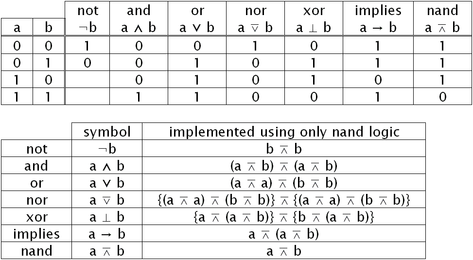
Truth Tables
References and Reference Materials
Reference Material
Added a pdfs directory in the cpu repository so that we can share documentation. In it is documentation for both cpus (8085 and 6502).
lab46:~/src/cpu$ mkdir pdfs
lab46:~/src/cpu$ svn add pdfs
A         pdfs
A  (bin)  pdfs/zaks_book.pdf
A  (bin)  pdfs/Using-6502-Assembly-Language-by-Randy-Hyde.pdf
A  (bin)  pdfs/8080-8085_assembly_language_programming__1977__intel__pdf_.pdf
A  (bin)  pdfs/ATARIAssemblerEditorReferenceCard.pdf
A  (bin)  pdfs/ATARIAssemblerEditorUsersManualUpdate.pdf
lab46:~/src/cpu$ svn commit -m "Created pdfs directory for cpu related pdfs -John Rine"
Adding         pdfs
Adding  (bin)  pdfs/8080-8085_assembly_language_programming__1977__intel__pdf_.pdf
Adding  (bin)  pdfs/ATARIAssemblerEditorReferenceCard.pdf
Adding  (bin)  pdfs/ATARIAssemblerEditorUsersManualUpdate.pdf
Adding  (bin)  pdfs/Using-6502-Assembly-Language-by-Randy-Hyde.pdf
Adding  (bin)  pdfs/zaks_book.pdf
Transmitting file data .....
Committed revision 143.
References
6502
- http://www.youtube.com/watch?v=HW9AWBFH1sA - Reverse Engineering the 6502
- http://www.youtube.com/watch?v=9hLGvLvTs1w -6502 Assembler
8085
Other References
Login Problems
Some people have reported problems logging into the wiki. There seems to be two sources of problems experienced:
- User cannot log in.
- User cannot log in using “Secure Login”.
If you are confident you are using the correct username and password, and are using a version of Internet Explorer, it is suggested that you use a different browser, such as Firefox, Safari, or Chrome.
If the “Secure Login” doesn't seem to be working for you, the behavior seems to occur when user passwords contain symbols like quote marks and asterisks. In which case, you can either:
- Uncheck “Use Secure Login”. This sort of defeats the purpose of having security though, so it isn't outwardly recommended.
- Change your password to something that doesn't contain quote marks or asterisks. We don't yet know exactly which characters cause this problem, but we suspect it is characters that aren't being properly escaped that could have special syntactical meaning.
Syntax
For those unfamiliar, here is a page on wiki editing syntax that can be used here.
Course Notes Wiki
This is a space for members of the Computer Organization class to create a source of information reflective and assisting to the course.
Aside from assignments that may have you specifically perform operations here, you should contribute when you encounter any of the following:
- Some neat bit of information related to the class
- Some clarification or understanding you've had with respect to concepts in the class
- Organizational/style improvements to existing content
- Questions you have that may deserve a more visual answer


