Table of Contents
Corning Community College
ENGR1050 C for Engineers
PROJECT: Voltage and Circuit Control (VCC1)
OBJECTIVE
To continue our exploration of interfacing electronics with our pi's, and writing a program that controls it, and collaboratively authoring and documenting the project and its specifications.
GRABIT
To assist with consistency across all implementations, data files for use with this project are available on lab46 via the grabit tool. Be sure to obtain it and ensure your implementation properly works with the provided data.
lab46:~/src/SEMESTER/DESIG$ grabit DESIG PROJECT
OVERVIEW
Your task is to expand upon last week's project by scaling it to six independently GPIO-controlled LEDs, optimize the binary counting process with a loop and bitwise logic, and to incorporate a button, which will influence the direction of counting (normal upward flow when not pressed, reverse flow during a button press).
Contributing to project documentation is also a core part of this project. If from reading the existing documentation or through your own exploring, you find something lacking, unclear, or outright missing, that is an opportunity to potentially contribute content.
You want the project documentation to provide you (as if coming in with no awareness of the project) with sufficient information so as to allow you to proceed. Asking questions on the discord is a great way of getting more information that you can use to add content.
EDIT
You will want to go here to edit and fill in the various sections of the document:
BACKGROUND
For this project we will be building off the previous project vcc0 and integrating a button into our circuit to allow the circuit to count up without input from the button and count backward while pressing the button.
BITWISE LOGIC OPERATORS
There are six bitwise logic operators. These operators work at bit-level and deal with the binary forms of numbers:
- & (bitwise AND) will compare each bit of two operands and give a result of 1 in that position if both operands have a 1 in that position.
- | (bitwise OR) will compare each bit of two operands and give a result of 1 in that position if either operand have a 1 in that position.
- ^ (bitwise XOR) will compare each bit of two operands and return a 1 in that position if one operand has a 1 in that position but the other does not
- « (left shift) will shift each bit of the first operand to the left by an amount equal to the second operand
- » (right shift) will shift each bit of the first operand to the right by an amount equal to the second operand
- ~ (bitwise NOT) will invert each bit of an operand.
To show these, let's take the numbers 60 (0011 1100) and 90 (0101 1010):
- x = 60 & 90 results in x = 24 (0001 1000)
- x = 60 | 90 results in x = 126 (0111 1110)
- x = 60 ^ 90 results in x = 102 (0110 0110)
- x = 60 « 2 results in x = 240 (1111 0000)
- x = 60 » 2 results in x = 15 (0000 1111)
- x = ~60 results in x = 195 (1100 0011)
ELECTRONICS
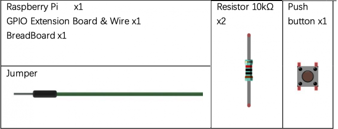
PARTS
BUTTON
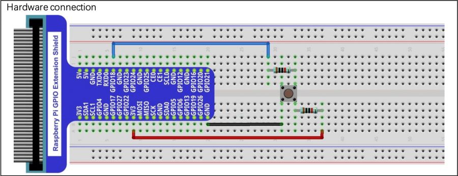
Here is a diagram for hooking up a button:
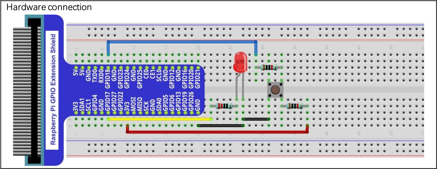
A possible manual test with an LED:
The main function of the button is to change the direction of the counting of the LED lights. In vcc1, like vcc0, you program the LED lights to count up to a certain number. In the vcc1, the LED lights count up to 64, and by pressing the button, the LED lights will count backwards from 63.
PROGRAM
The sample program in the project grabit will have the basic necessities to start off your program.
First step will be to change the definition (pin #) of your button.
Replace “num” with the wiringpi pin number of the GPIO for your button
#define BUTTON num
Now we have to set the number of LED's that we are connecting to our Pi to specify the size of our pin array.
Enter the number of LED's you are using, in the case of this project 6
#define NUM_LEDS 6
Next, we define our variables. The sample program already defines both our index int value as well as declaring our pin array for pin assignments. If you would like to define a different variable for your counter or for any other necessary variables, do it here.
Int container = 0; num_container = 32;
Now we have to set up our pin array. Much like the last project, you're assigning each pin an array assignment (0-6) within the array, then defining what Wiringpi pin it corresponds to. Remember to set your pin for your button as an input and your led pins as outputs.
Using
gpio readall
in your terminal can help you find both the BCM number and the corresponding wiringpi numbers.
pseudocode
SET COUNTER TO ZERO
AS LONG AS PROGRAM CONTINUES TO RUN:

    SET VALUE TO CURRENT NUMBER STORED IN COUNTER

    LOOKING AT BITS RANGING FROM NUM_LEDS MINUS ONE TO ZERO:

        SET PLACEVALUE TO TWO RAISED TO THE BIT BEING LOOKED AT
        SHOULD VALUE ANDED WITH PLACEVALUE BE ONE:
            ENABLE PLACEVALUE'S LED
        OTHERWISE:
            DISABLE PLACEVALUE'S LED

    NEXT LOOK (UNTIL DONE)

    SHOULD THE BUTTON BE PRESSED:
        UPDATE COUNTER TO BE ONE LESS THAN ITS CURRENT STATE
        SHOULD THE COUNTER GO BELOW ZERO:
            RESET COUNTER TO TWO RAISED TO NUM_LEDS

    OTHERWISE:
        UPDATE COUNTER TO BE ONE GREATER THAN ITS CURRENT STATE
        SHOULD THE COUNTER EXCEED FIFTEEN:
            RESET COUNTER TO ZERO

KEEP GOING
SUBMISSION
To be successful in this project, the following criteria (or their equivalent) must be met:
- Project must be submit on time, by the deadline.
- Late submissions will lose 33% credit per day, with the submission window closing on the 3rd day following the deadline.
- All code must compile cleanly (no warnings or errors)
- Compile with the -Wall and –std=gnu18 compiler flags
- all requested functionality must conform to stated requirements (either on this document or in a comment banner in source code files themselves).
- Executed programs must display in a manner similar to provided output
- output formatted, where applicable, must match that of project requirements
- Processing must be correct based on input given and output requested
- Output, if applicable, must be correct based on values input
- Code must be nicely and consistently indented
- Code must be consistently written, to strive for readability from having a consistent style throughout
- Code must be commented
- Any “to be implemented” comments MUST be removed
- these “to be implemented” comments, if still present at evaluation time, will result in points being deducted.
- Sufficient comments explaining the point of provided logic MUST be present
- No global variables (without instructor approval), no goto statements, no calling of main()!
- Track/version the source code in your lab46 semester repository
- Submit a copy of your source code to me using the submit tool (make submit on lab46 will do this) by the deadline.
Submit Tool Usage
Let's say you have completed work on the project, and are ready to submit, you would do the following (assuming you have a program called uom0.c):
lab46:~/src/SEMESTER/DESIG/PROJECT$ make submit
You should get some sort of confirmation indicating successful submission if all went according to plan. If not, check for typos and or locational mismatches.
RUBRIC
I'll be evaluating the project based on the following criteria:
65:vcc1:final tally of results (65/65)
*:vcc1:used grabit to obtain project by the Sunday prior to duedate [10/10]
*:vcc1:picture of unpowered circuit to #desig for approval [10/10]
*:vcc1:picture of powered circuit to #desig showing results [10/10]
*:vcc1:clean compile, no compiler messages [7/7]
*:vcc1:program conforms to project specifications [22/22]
*:vcc1:code tracked in lab46 semester repo [6/6]
Pertaining to the collaborative authoring of project documentation
- each class member is to participate in the contribution of relevant information and formatting of the documentation
- minimal member contributions consist of:
- near the class average edits (a value of at least four productive edits)
- near the average class content change average (a value of at least 256 bytes (absolute value of data content change))
- near the class content contribution average (a value of at least 1kiB)
- no adding in one commit then later removing in its entirety for the sake of satisfying edit requirements
- adding and formatting data in an organized fashion, aiming to create an informative and readable document that anyone in the class can reference
- content contributions will be factored into a documentation coefficient, a value multiplied against your actual project submission to influence the end result:
- no contributions, co-efficient is 0.50
- less than minimum contributions is 0.75
- met minimum contribution threshold is 1.00
Additionally
- Solutions not abiding by spirit of project will be subject to a 50% overall deduction
- Solutions not utilizing descriptive why and how comments will be subject to a 25% overall deduction
- Solutions not utilizing indentation to promote scope and clarity or otherwise maintaining consistency in code style and presentation will be subject to a 25% overall deduction
- Solutions not organized and easy to read (assume a terminal at least 90 characters wide, 40 characters tall) are subject to a 25% overall deduction


