Table of Contents
Corning Community College
ENGR1050 C for Engineers
PROJECT: Voltage and Circuit Control (VCC0)
OBJECTIVE
To begin our exploration of interfacing electronics with our pi's, and writing a program that controls it, and collaboratively authoring and documenting the project and its specifications.
GRABIT
To assist with consistency across all implementations, data files for use with this project are available on lab46 via the grabit tool. Be sure to obtain it and ensure your implementation properly works with the provided data.
lab46:~/src/SEMESTER/DESIG$ grabit DESIG PROJECT
OVERVIEW
Your task is write a program that drives four LEDs through a binary counting process, constantly counting from 0-15 (over and over), until interrupted.
Contributing to project documentation is also a core part of this project. If from reading the existing documentation or through your own exploring, you find something lacking, unclear, or outright missing, that is an opportunity to potentially contribute content.
You want the project documentation to provide you (as if coming in with no awareness of the project) with sufficient information so as to allow you to proceed. Asking questions on the discord is a great way of getting more information that you can use to add content.
EDIT
You will want to go here to edit and fill in the various sections of the document:
BACKGROUND
SELECTION LOGIC
RELATIONAL OPERATORS
| Operator | Description | Example |
|---|---|---|
| == | Checks if the values are equal or not, If yes, condition is true | (A == B) |
| != | Checks if the values are equal or not, If values are not equal, then condition is true | (A != B) |
| > | Checks if the value of left operand is greater than the value of right operand | (A > B) |
| < | Checks if the value of the left operand is less than the value of right operand | (A < B) |
| >= | Checks if the value of left operand is greater than or equal to the value of the right operand | (A >= B) |
| ⇐ | Checks if the value of left operand is less than or equal to the value of the right operand | (A ⇐ B) |
WIRINGPI INSTALL
In order to navigate successfully throughout the wiringPi library in the command-line, a few key functions are going to be needed:
gpio readall: This allows view of the table that correlates to the pins and positions on the breadboard. It gives the pin number in terms of what the Pi reads and in terms of what code for the project reads. It allows tells whether the pin is in Input mode or Output mode.
gpio mode: This allows one to change the mode of specific pins from Input to Output and visa versa. Once the command is typed, it will ask for the desired pin number (found in the readall table) and the desired mode (In/Out).
gpio write: Once the desired pins have been hooked up on the breadboard and configured on the Pi, this function is used to switch between supplying voltage or not. Once typed, it will ask for the desired pin (which should already be configured) and a choice of 0(off) and 1(on).
ELECTRONICS
BREADBOARD
The breadboard is the device we will use to build our circuits:
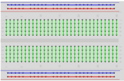
The electrical layout of the breadboard is as follows:
Here's a good video overview of the functionality of a breadboard:
The purpose of the breadboard is to make quick electrical connections between components- like resistors, LEDs, capacitors, etc- so that you can test your circuit before permanently soldering it together. Breadboards have many small sockets on them, and some groups of sockets are electrically connected to each other. On the underside of the board there are many small metal strips which physically connect certain groups of sockets together and allow electricity to flow freely between them. These strips are probably not visible on the underside of your breadboard.
COMPONENTS
Breadboard
A breadboard consists of plastic block holding a matrix of electrical sockets of a size suitable for gripping thin connecting wire, component wires or the pins of transistors and integrated circuits. The sockets are connected inside the board (by metal clips), in rows of five sockets horizontally.
GPIO Expansion Board
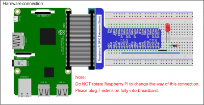
The GPIO Expansion board connects to the pins of your pi via a ribbon cable. The GPIO expansion board is then fitted onto the breadboard making the functionality of the pins available to use on the breadboard.
220 ohm resistors x4
Resistors limit or regulate the flow of electrical current in an electronic circuit. Too much current going to the LED can cause the LED to burn out as LEDs will take as much current as you give them, but not without a price. Limiting the current to the LED bulb using a resistor ensures that we supply enough current to light the bulb without supplying too much current burning out the bulb.
Jumper leads
Jumper leads are wires used to connect to the load components (LEDs) to the GPIO BCM pins.
CIRCUIT
ONE LED
Here is a diagram for a circuit driving one LED, from one GPIO pin:
You are after a circuit that drives four LEDs, each one from a unique GPIO pin.
FOUR LED
You will want to identify 2 additional GPIO pins (The example program has BCM 17 and 18 already included to run as an output) and you can identify the wiringpi pin number/BCM number by using
yourpi:~$ gpio readall
This will give you what your machine has for GPIO's, what the BCM Pin number is, as well as what the wiringpi pin number is. Each LED will require a GPIO power jumper wire, a resistor, and a ground. You can either use a different ground pin for each or simply use one ground pin ran to the ground rail on either side of the breadboard then ground all LEDs to the ground rail. Arranging your LEDs in a straight line of 4 is ideal as you will have each binary digit represented in order from right to left.
SPECIFICATIONS
PI SETUP
NOTE: As of 20220908, is not working for the pi 400. See the section below for the pi 400 workaround.
First, we need to download the wiringPi library package:
yourpi:~$ wget https://project-downloads.drogon.net/wiringpi-latest.deb
Then, we need to install it:
yourpi:~$ sudo dpkg -i wiringpi-latest.deb
wiringPi on the pi400
For the pi400, we have to do a slightly different process, but will result in the needed functionality becoming available.
On the pi (doesn't matter where, although probably NOT in your repository; base of home directory works fine):
yourpi~$ git clone https://github.com/WiringPi/WiringPi.git
Then:
yourpi:~$ cd WiringPi
yourpi:~/WiringPi$
Finally, build and install it:
yourpi:~/WiringPi$ ./build
Provided there are no apparent errors, close out of that terminal and open a new one, then the gpio tool and related WiringPi functionality should now be available.
PROGRAM
Declare int cont = 0; int num_cont = 8:
Make sure to record wiring pi assignments into pin array. Ex: pin[0] = 0 pin[1] = 2 pin[2] = 3 pin[3] = 4
Remember to use if and else statements in while statement. Digital write goes after all if and else statements. Else uses LOW meaning off and if uses HIGH meaning on.
pseudocode
SET COUNTER TO ZERO
AS LONG AS PROGRAM CONTINUES TO RUN:

    SET VALUE TO CURRENT NUMBER STORED IN COUNTER

    SHOULD THE VALUE CONTAIN AN EIGHT:
        UPDATE VALUE TO ITSELF MINUS EIGHT
        ENABLE THE EIGHT'S PLACE LED
    OTHERWISE:
        DISABLE THE EIGHT'S PLACE LED

    SHOULD THE VALUE CONTAIN A FOUR:
        UPDATE VALUE TO ITSELF MINUS FOUR
        ENABLE THE FOUR'S PLACE LED
    OTHERWISE:
        DISABLE THE FOUR'S PLACE LED

    SHOULD THE VALUE CONTAIN A TWO:
        UPDATE VALUE TO ITSELF MINUS TWO
        ENABLE THE TWO'S PLACE LED
    OTHERWISE:
        DISABLE THE TWO'S PLACE LED

    SHOULD THE VALUE CONTAIN A ONE:
        UPDATE VALUE TO ITSELF MINUS ONE
        ENABLE THE ONE'S PLACE LED
    OTHERWISE:
        DISABLE THE ONE'S PLACE LED

    UPDATE COUNTER TO BE ONE GREATER THAN ITS CURRENT STATE
    SHOULD THE COUNTER EXCEED FIFTEEN:
        RESET COUNTER TO ZERO
SUBMISSION
To be successful in this project, the following criteria (or their equivalent) must be met:
- Project must be submit on time, by the deadline.
- Late submissions will lose 33% credit per day, with the submission window closing on the 3rd day following the deadline.
- All code must compile cleanly (no warnings or errors)
- Compile with the -Wall and –std=gnu18 compiler flags
- all requested functionality must conform to stated requirements (either on this document or in a comment banner in source code files themselves).
- Executed programs must display in a manner similar to provided output
- output formatted, where applicable, must match that of project requirements
- Processing must be correct based on input given and output requested
- Output, if applicable, must be correct based on values input
- Code must be nicely and consistently indented
- Code must be consistently written, to strive for readability from having a consistent style throughout
- Code must be commented
- Any “to be implemented” comments MUST be removed
- these “to be implemented” comments, if still present at evaluation time, will result in points being deducted.
- Sufficient comments explaining the point of provided logic MUST be present
- No global variables (without instructor approval), no goto statements, no calling of main()!
- Track/version the source code in your lab46 semester repository
- Submit a copy of your source code to me using the submit tool (make submit on lab46 will do this) by the deadline.
Submit Tool Usage
Let's say you have completed work on the project, and are ready to submit, you would do the following (assuming you have a program called uom0.c):
lab46:~/src/SEMESTER/DESIG/PROJECT$ make submit
You should get some sort of confirmation indicating successful submission if all went according to plan. If not, check for typos and or locational mismatches.
RUBRIC
I'll be evaluating the project based on the following criteria:
52:vcc0:final tally of results (52/52)
*:vcc0:used grabit to obtain project by the Sunday prior to duedate [6/6]
*:vcc0:picture of unpowered breadboard to #desig for approval [7/7]
*:vcc0:picture of powered breadboard to #desig showing results [6/6]
*:vcc0:clean compile, no compiler messages [7/7]
*:vcc0:program conforms to project specifications [20/20]
*:vcc0:code tracked in lab46 semester repo [6/6]
Pertaining to the collaborative authoring of project documentation
- each class member is to participate in the contribution of relevant information and formatting of the documentation
- minimal member contributions consist of:
- near the class average edits (a value of at least four productive edits)
- near the average class content change average (a value of at least 256 bytes (absolute value of data content change))
- near the class content contribution average (a value of at least 1kiB)
- no adding in one commit then later removing in its entirety for the sake of satisfying edit requirements
- adding and formatting data in an organized fashion, aiming to create an informative and readable document that anyone in the class can reference
- content contributions will be factored into a documentation coefficient, a value multiplied against your actual project submission to influence the end result:
- no contributions, co-efficient is 0.50
- less than minimum contributions is 0.75
- met minimum contribution threshold is 1.00
Additionally
- Solutions not abiding by spirit of project will be subject to a 50% overall deduction
- Solutions not utilizing descriptive why and how comments will be subject to a 25% overall deduction
- Solutions not utilizing indentation to promote scope and clarity or otherwise maintaining consistency in code style and presentation will be subject to a 25% overall deduction
- Solutions not organized and easy to read (assume a terminal at least 90 characters wide, 40 characters tall) are subject to a 25% overall deduction


