Table of Contents
Corning Community College
ENGR1050 C for Engineers
PROJECT
PROJECT: Light Emitting Diodes (led2)
Objective
To expand upon our previous efforts, through wiring up a 10 LED block package and extending/optimizing our previous binary count from led1 (extend from 4-bits to 10-bits, and utilize a loop to better optimize your logic)
We continue to utilize time constraints, tying project credit to your starting on the project before the deadline (so be sure to plan accordingly!)
Abstraction
As an exercise in toning your abstraction abilities (literally seeing one thing, but understanding and using it as something else), there will be a number of 'generic' terms used throughout this (and other) documents throughout the course, requiring you to substitute in the pertinent information (else face confusion or error).
Some examples:
- yourusername - where you see this (likely in a config file or command-line argument), you are NOT to literally type in y-o-u-r-u-s-e-r-n-a-m-e, but instead, substitute in YOUR lab46 username.
- desig - different classes have different class designations. To make one universal document pertinent to ALL classes, specific examples will instead use 'desig', where you must substitute in the class desig of the class YOU are taking and acting upon in that moment. Example class desigs:
- c4eng - ENGR1050 “C for Engineers”
- cprog - CSCS1320 “C/C++ Programming”
- unix - CSCS1730 “UNIX/Linux Fundamentals”
- data - CSCS2320 “Data Structures”
- discrete - CSCS2330 “Discrete Structures”
- comporg - CSCS2650 “Computer Organization”
- sysprog - CSCS2730 “Systems Programming”
This sort of abstraction is very similar to that we will find in our utilization of variables in programming, where we can have a “name”, but the data associated with it can change based on various conditions.
Do not be a literalist computer! Start to exercise your abstraction abilities.
Locational Awareness
This document is written with TWO locations in mind:
- lab46 (the system you may retrieve resources and SUBMIT projects)
- identified in examples with the use of the lab46:~$ prompt
- your pi (the system you will transfer resources to/from, and WORK ON/COMPLETE projects)
- identified in examples with the use of the yourpi:~$ prompt
There are commands you can ONLY run on one system or the other. Pay attention to any prompt cues in the given examples (or section headings, context of language leading up to any examples).
For example:
- YOU cannot install software on lab46. You don't have access.
- projects CANNOT be SUBMITTED on your pi.
Please pay attention to your prompt, so you can perform the needed activity on the correct system.
Reading
Please be sure to familiarize yourself with the following content in “the C book”:
Background
For this project, you will be working with a C program using the wiringPi library on the Raspberry Pi, wiring up a 10 LED block package to your breadboard and witnessing your ability to control them via software.
Input and Output via the GPIO pins on the pi
One of the intended uses of the Raspberry Pi and other small, single board computers is as an interface tool to peripherals in projects, personal and industrial.
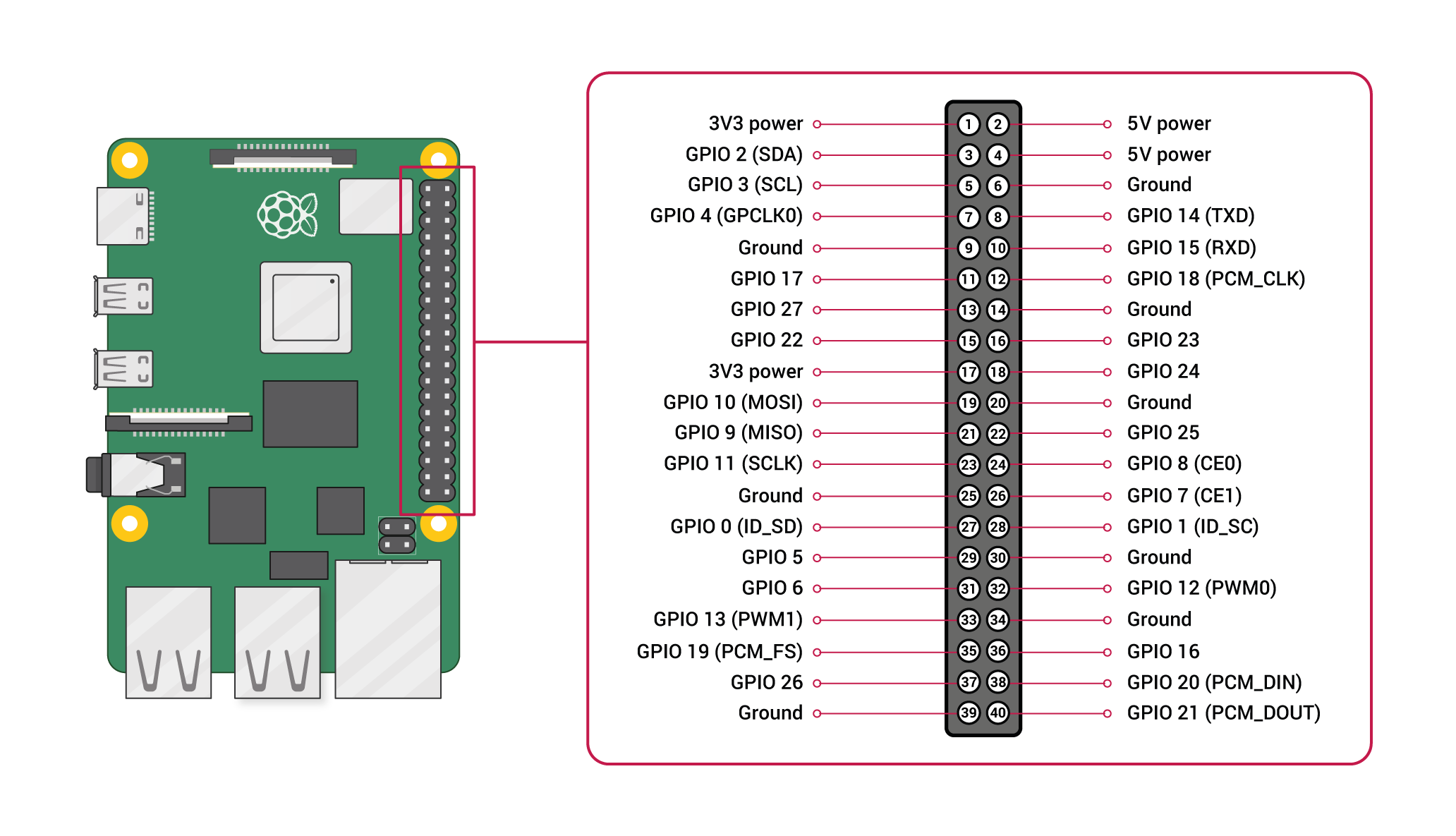
The pi has a set of General Purpose Input Output (GPIO) pins intended for precisely this purpose:
Please note the orientation of the pi (ethernet/USB at bottom) to calibrate yourself to the location of pin 1 and all subsequent pins, along with their identified function (ie top left pin, pin 1, provides a constant 3.3v DC power)
You will want to verify placement before supplying power, that is why we are taking things slow, and providing you opportunities to confirm (by posting pictures in the discord channel) before proceeding.
Wiring up our circuit
This circuit is essentially an expansion upon the one you made last week (four individual LED circuits). So the parts needed remains the same, save for swapping out the discrete LEDs for an all-in-one 10 LED block package, which should marginally simplify aspects of circuit construction.
In this project, we will be hooking up a peripheral to some of our Raspberry Pi pins: light emitting diodes (LED) and supporting hardware, and then proceed to interface with them to control its state (of being ON or OFF).
You have likely encountered LEDs endlessly in your everyday life: commonly used as a “power light”, which when lit, indicates the device is powered on, among many, MANY, MANY other applications.
For this endeavour, you will need to obtain the following items out of the electronics kit you obtained for the class:
(1) breadboard
In your electronics kit, what will serve as the base, or mounting point for our electronic circuits, will be the solderless breadboard, which resembles the following:
We will be inserting the metal legs of various components in various holes on the breadboard, to connect our circuit together.
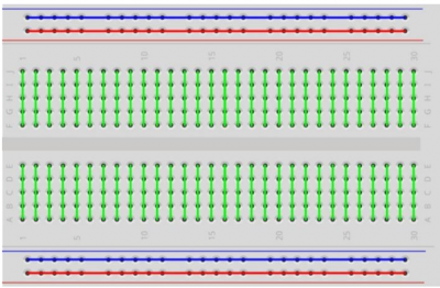
On the breadboard, there are 2 different pathways of connectivity. If you look along the top and bottom of the breadboard, do you see the red and blue strip running horizontal across the board? That means that ALL pins in that row are hooked together (all the pins along the blue line are hooked together with each other, all the pins along the red lines are hooked together with each other). We will be using that to to provide things like a common voltage (+) or a common ground (-) to components that need such things.
In the middle of the breadboard, separated by the valley in the plastic molding, are columns of connected pins (unique columns, also separate from the other side of the valley). Each group of those 5 pins is hooked together.
You'll notice occasional “by 5” counting off silkscreened on the breadboard, which can be used to try to keep things organized.
Here's a logical diagram of the breadboard layout:
Here's a good video overview of the functionality of a breadboard:
(1) T-cobbler and data cable
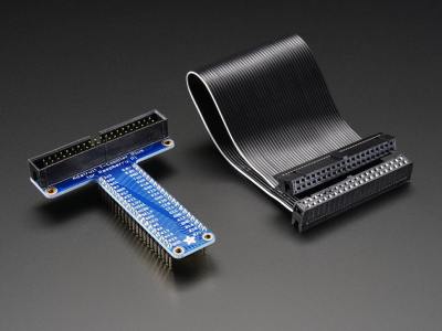
In your kit should be a T-shaped device (known as the “T-cobbler” with some aspect of pin names silkscreened on it, and a 40-pin ribbon cable). Colors may vary, but essentially it looks like this:
Note that the T-cobbler, on top has a set of pins, enclosed in a plastic rectangle, shaped to fit the ribbon cable.
The plastic rectangle should have a notch cut out from it, and notice that the ribbon cable connector has a notch included in it. That is a key to indicate how you need to connect the ribbon cable into the T-cobbler
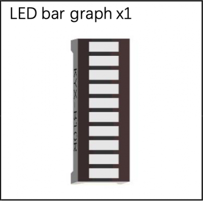
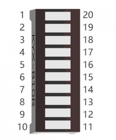
(1) 10 LED block package
10 LEDs, all in one convenient package!
The package has a set of pins, which allow us to hook each LED up as we would if they were separate:
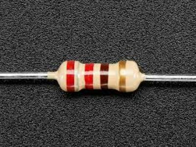
(10) 220 Ohm resistors
Your kit should come with 3-4 packs of differently rated resistors (220, 1K, and 10K). You want TEN of the lowest rated ones, the 220 ohm variety. One for each LED. You should see the value marked on the paper strip holding the legs of the resistors.
The color bands are important, not the body color itself. You resistor body may be beige, may be blue, but the color of the 4-5 rings is what is important. Here we have red (2), red (2), brown (x10); 22 * 10 = 220
Unlike the LED, where the direction of connection matters, it does not matter which way you plug in a resistor. Its purpose is simply to resist.
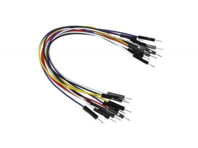
male to male jumper wire, as needed
As a final piece of equipment you will need, locate and have a few male-to-male jumper wires handy for use in our circuit:
The Circuit to Construct
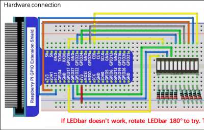
With those components, you will want to place them onto your breadboard, in a manner similar to last week's circuit, but obviously with a lot more going on. Here is the circuit diagram you are assembling:
Take note of how everything is being plugged in, and what connection on the T-cobbler is being utilized.
Please keep in mind:
- EACH LED needs to be interfaced with a unique GPIO pin
- EACH LED needs a corresponding resistor (no sharing!) Forgetting to use the resistor can lead to damage to the LED!
- take note of which GPIO pin you are using, so you can update the led2.c program accordingly
Before you seek to actually test your circuit, please get verification to proceed from the class channel on discord by posting a clear picture of everything. There are MANY parts, and especially as we have our first exposure, it is best to insert as many quality control checks as possible to ensure the greatest chances of mistakes are mitigated.
Testing connectivity
To verify whether everything is hooked up correctly (including the correct positioning of the LED), please try the following:
Set wiringPi pin 0 to OUTPUT mode
Remember in that big readout of all the gpio pins above? Take a look at the settings for wiringPi pin 0:
 +-----+-----+---------+------+---+---Pi 4B--+---+------+---------+-----+-----+
 | BCM | wPi |   Name  | Mode | V | Physical | V | Mode | Name    | wPi | BCM |
 +-----+-----+---------+------+---+----++----+---+------+---------+-----+-----+
 | ...
 |  17 |   0 | GPIO. 0 |   IN | 0 | 11 |
Note that, currently wPi pin 0 is set to INPUT (with no voltage). We need to change that to OUTPUT, which you can do by doing the following:
yourpi:~/src/SEMESTER/DESIG/led2$ gpio mode 0 OUT
At which point that particular pin will be changed from IN to OUT:
 +-----+-----+---------+------+---+---Pi 4B--+---+------+---------+-----+-----+
 | BCM | wPi |   Name  | Mode | V | Physical | V | Mode | Name    | wPi | BCM |
 +-----+-----+---------+------+---+----++----+---+------+---------+-----+-----+
 | ...
 |  17 |   0 | GPIO. 0 |  OUT | 0 | 11 |
Okay, output mode enabled, now to twiddle the bits off and on:
yourpi:~/src/SEMESTER/DESIG/led2$ gpio write 0 1      ## activate voltage on wiringpi pin 0 (turn on)
yourpi:~/src/SEMESTER/DESIG/led2$ gpio write 0 0      ## deactivate voltage on wiringpi pin 0 (turn off)
If your LED is hooked up correctly, the LED should light up, ideally during the ON line.
If you get no activity out of the LED, try reversing it and try again.
With an expanded set of LED circuits, be sure to test the operation of each one.
Program
It is your task to write program to interface with your expanded set of LEDs (light emitting diodes), a nice software-hardware connection, on your raspberry pi.
You aim for this project is to write a program that will get all 10 LEDs in the LED bar to “count” (in binary) from 0 to the maximum supported value:
- with 4 LEDs, that meant 4 bits: 2^4=16, so 0-15.
- with 10 LEDs, that means 10 bits: 2^10=1024, so 0-1023.
- initially start with all LEDs off (displaying the zero value)
- one “number” at a time (on a constant update delay) activate the various LEDs to represent the number intended to be displayed
Your 4 LED implementation in led1, targetting if() statements, may well have involved addressing 16 distinct cases (one for each “number”). Retaining that exact same approach for this project would be far more time-consuming here, as you'd then have to support 1024 cases. As such, you will want to utilize a loop to drive a variable through one common block of code, updating each LED as appropriate for the number being displayed.
In addition to the top-level while(1) infinite loop keeping the program going, you want to use an additional loop to optimize your counting process (located within that top-level while(1) loop).
Grabbing project resources (on lab46)
I have prepared a grabit for resources related to this project. To obtain:
lab46:~/src/SEMESTER/DESIG$ grabit desig led2
make: Entering directory '/var/public/SEMESTER/DESIG/led2'
'/var/public/SEMESTER/DESIG/led2/Makefile' -> '/home/user/src/SEMESTER/DESIG/led2/Makefile'
'/var/public/SEMESTER/DESIG/led2/led2.c' -> '/home/user/src/SEMESTER/DESIG/led2/led2.c'
make: Leaving directory '/var/public/SEMESTER/DESIG/led2'
lab46:~/src/SEMESTER/DESIG$
At which point you can change into the newly created and populated led2 directory.
Getting project resources from lab46 to your pi
Okay, you've snagged the project files on lab46. Now, how to get them to your pi?
The same way you've been juggling project files already, by using your mercurial repository!
Using the hg tool, be sure to add, commit, and push successfully on lab46.
Then, over on your pi, use hg to pull and update the new changes into place. Then you can proceed.
Compiling
Since the grabit brought in a Makefile, you can compile your code simply by typing: make
Any compiler errors will go into a text file called errors
To do a full cleaning, run: make clean then make (or make debug)
If you'd like to see compiler messages as you compile, run: make debug
When done and ready to submit, on lab46: make submit
Number weights
Looking at a binary number, considering the weights of the various places, we can glean some valuable details:
- The binary numbers 0000 (0) and 0001 (1) are both less than 2.
- The binary numbers 0010 (2) and 0011 (3) are both less than 4.
- The binary numbers 0100 (4), 0101 (5), 0110 (6), and 0111 (7) are all less than 8.
The number 12 in binary (1100), when 8 (1000) is subtracted is: 4 (0100).
The number 13 in binary (1101), CAN have 8 subtracted from it, CAN have 4 subtracted from it, CANNOT have 2 subtracted from it, and CAN have 1 subtracted from it.
Looking at the place values/weights:
2^3  2^2  2^1  2^0
 8    4    2    1
When you have a number like 13 (1101), notice that:
1 1 0 1
^ ^ ^ ^
| | | |
| | | +-- 1 x 2^0 (1) = 1
| | +---- 0 x 2^1 (2) = 0
| +------ 1 x 2^2 (4) = 4
+-------- 1 x 2^3 (8) = 8

8 + 4 + 1 = 13
Notice how the number 13 contains an 8, a 4, and a 1.
- Because it contains an 8, we light up the LED for that 2^3 position
- Because then it contains a 4, we light up the LED for 2^2
- Since it does NOT contain a 2, we do NOT light up the LED for 2^1
- Finally, we check to see if there's a 1, and since there is, we light up the LED for 2^0
Bitwise logic
Since the off/on state of each LED is essentially binary in nature (or one bit of an overall sequence), why not utilize the powerful bitwise tools available to us in C?
bitwise-AND
C provides a bitwise AND operator, the & symbol, which can be used in equations to perform bitwise-AND operations:
char value  = 5;         // 00000101 in binary
value       = value & 6; //   00000101
                         // & 00000110
                         //   ========
                         //   00000100
Remember the truth table for the AND:
( AND )
A B | X
====+===
F F | F
F T | F
T F | F
T T | T
Think of how this property could be used in combination with other concepts we've learned about in C to solve the problem at hand.
bitwise-iOR
C provides a bitwise inclusive OR operator, the | symbol, which can be used in equations to perform bitwise-iOR operations:
char value  = 5;         // 00000101 in binary
value       = value | 6; //   00000101
                         // | 00000110
                         //   ========
                         //   00000111
Remember the truth table for the iOR:
( iOR )
A B | X
====+===
F F | F
F T | T
T F | T
T T | T
Think of how this property could be used in combination with other concepts we've learned about in C to solve the problem at hand.
bitwise-xOR
C provides a bitwise exclusive OR operator, the ^ symbol, which can be used in equations to perform bitwise-xOR operations:
char value  = 5;         // 00000101 in binary
value       = value ^ 6; //   00000101
                         // ^ 00000110
                         //   ========
                         //   00000011
Remember the truth table for the xOR:
( xOR )
A B | X
====+===
F F | F
F T | T
T F | T
T T | F
Think of how this property could be used in combination with other concepts we've learned about in C to solve the problem at hand.
logical shifting
C also allows for bitwise shifting, in the left or right direction:
char value  = 1; // 0001

value = value << 1; // left shift by 1 bit: 0001 -> 0010
char value  = 8; // 1000

value = value >> 1; right shift by 1 bit: 1000 -> 0100
Process
The general flow of the process (one way of going about it, anyway) can be described as follows:
number <- 0
loop (endlessly)
    loop through the numbers in the range being evaluated
        calculate the value representing the max place being checked (2 raised to LED number)
        if (the current number contains that place being checked)
            activate the LED representing that place
            adjust/remove that place value from current number being checked
        else
            deactivate the LED representing that place
        endif

        calculate the value representing the next place being checked (2 raised to next lower LED number)
        if (the current number contains that place being checked)
            activate the LED representing that place
            adjust/remove that place value from current number being checked
        else
            deactivate the LED representing that place
        endif

        ... etc. through to the final LED position ...

        strategic delay so you can see the manifested representation of the current number
    done
done
Submission
To successfully complete this project, the following criteria must be met:
- Code must compile cleanly (no notes, warnings, nor errors)
- Output must be correct, and match the form given in the sample output above.
- Code must be nicely and consistently indented
- Code must be well commented
- Do NOT double space your code. Group like statements together.
- Output Formatting (including spacing) of program must conform to the provided output (see above).
- Track/version the source code in a repository
- Submit a copy of your source code to me using the submit tool.
- Post required images and obtain needed confirmation to proceed from me on class channel on discord.
To submit this program to me using the submit tool, run the following command at your lab46 prompt:
lab46:~/src/SEMESTER/DESIG/led2$ make submit
You should get some sort of confirmation indicating successful submission if all went according to plan. If not, check for typos and or locational mismatches.
What I'll be looking for:
52:led2:final tally of results (52/52)
*:led2:post picture of unpowered layout to #desig and get approval [6/6]
*:led2:post picture to #desig by Sunday before deadline [6/6]
*:led2:post picture of powered LEDs in layout to #desig [6/6]
*:led2:grabit on the code on lab46 by Sunday before deadline [6/6]
*:led2:led2.c code adequately modified per project requirements [12/12]
*:led2:led2.c algorithm makes central use of a loop to drive process [8/8]
*:led2:led2.c comments describing what is happening [4/4]
*:led2:updated code is pushed to lab46 repository [4/4]
Additionally:
- Solutions not abiding by spirit of project will be subject to a 25% overall deduction
- Solutions not utilizing descriptive why and how comments will be subject to a 25% overall deduction
- Solutions not utilizing indentation to promote scope and clarity will be subject to a 25% overall deduction
- Solutions not organized and easy to read are subject to a 25% overall deduction
